Assembling the Xii-Boy Ultra
Top Half Assembly
Installing the Display
- Peel off the film covering the front of the glass.

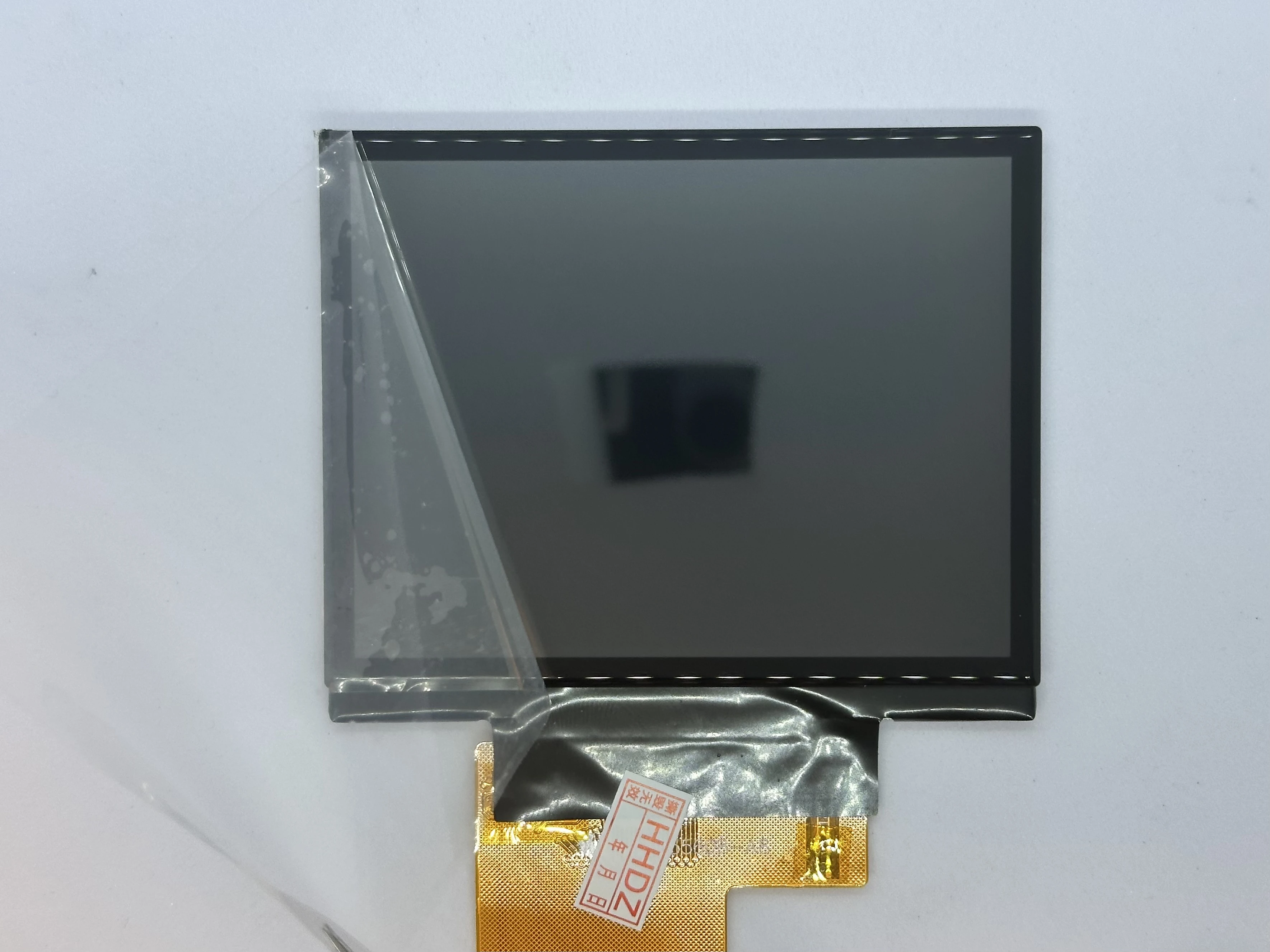
- Place the display into the top shell at a 45° angle. The bottom of the display should sit flat on the indent of the case, and the ribbon cable should go through to the inside.
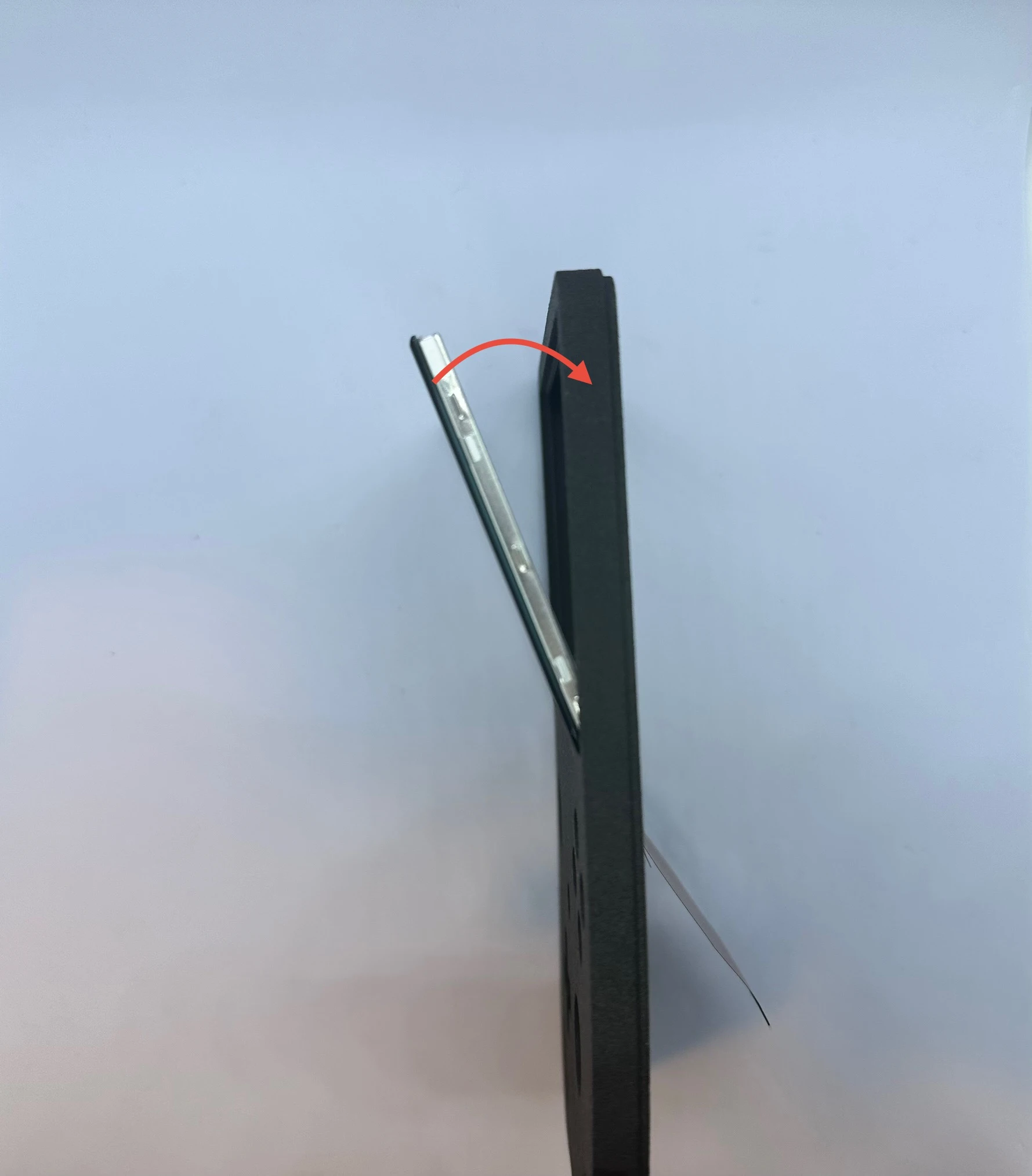
- Slowly rotate the screen toward the front of the shell. At the very end, a small amount of force may be required to set the display in place. A small lip surrounds the indent, and you may hear a soft “click” as the display snaps into place.
NOTICE
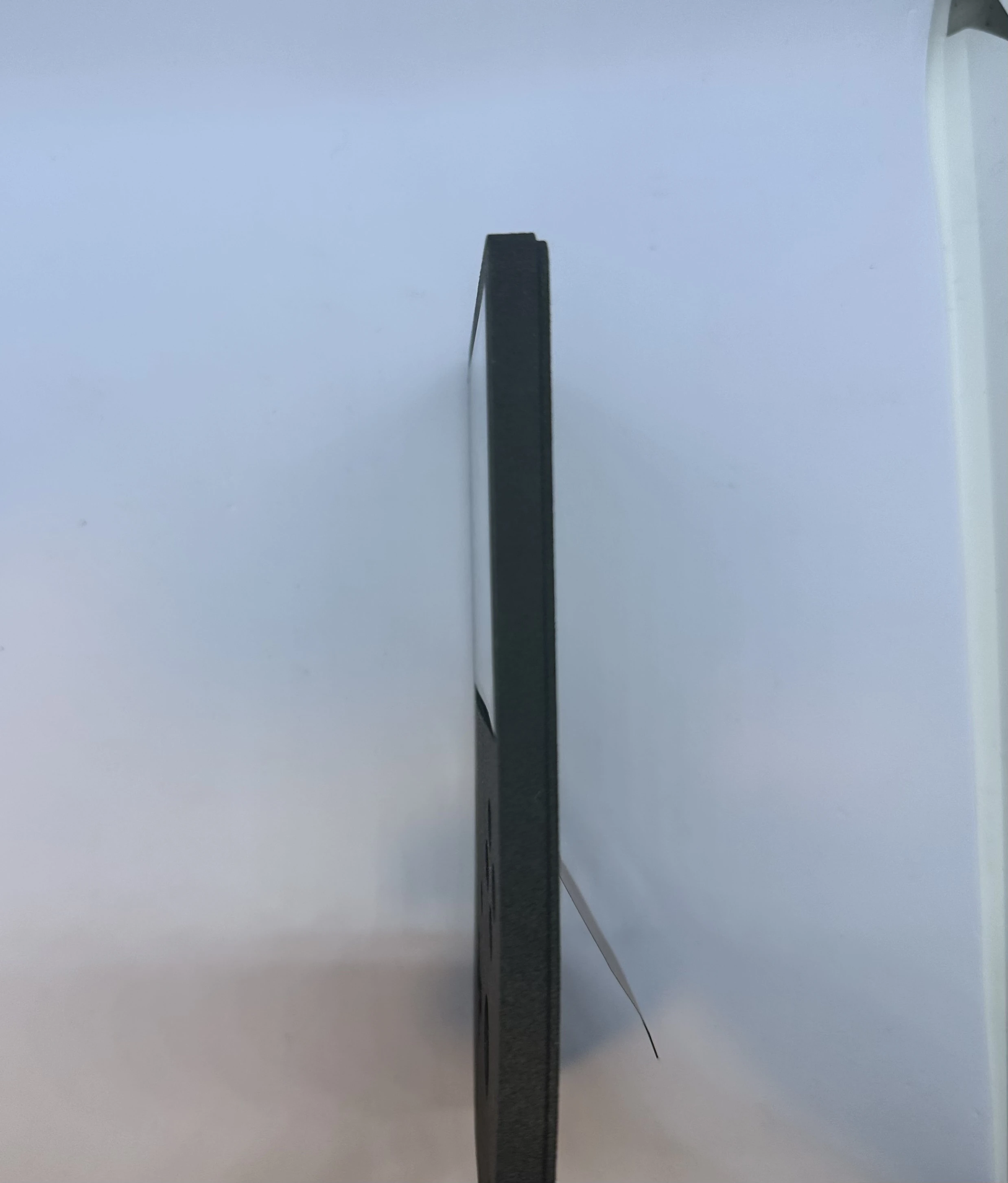
After the click, the display will be held in by friction and the lip. It is not recommended to remove the display more than once or twice, as this can cause issues with the fitting.
Xii-DD PCB (XBU-002)
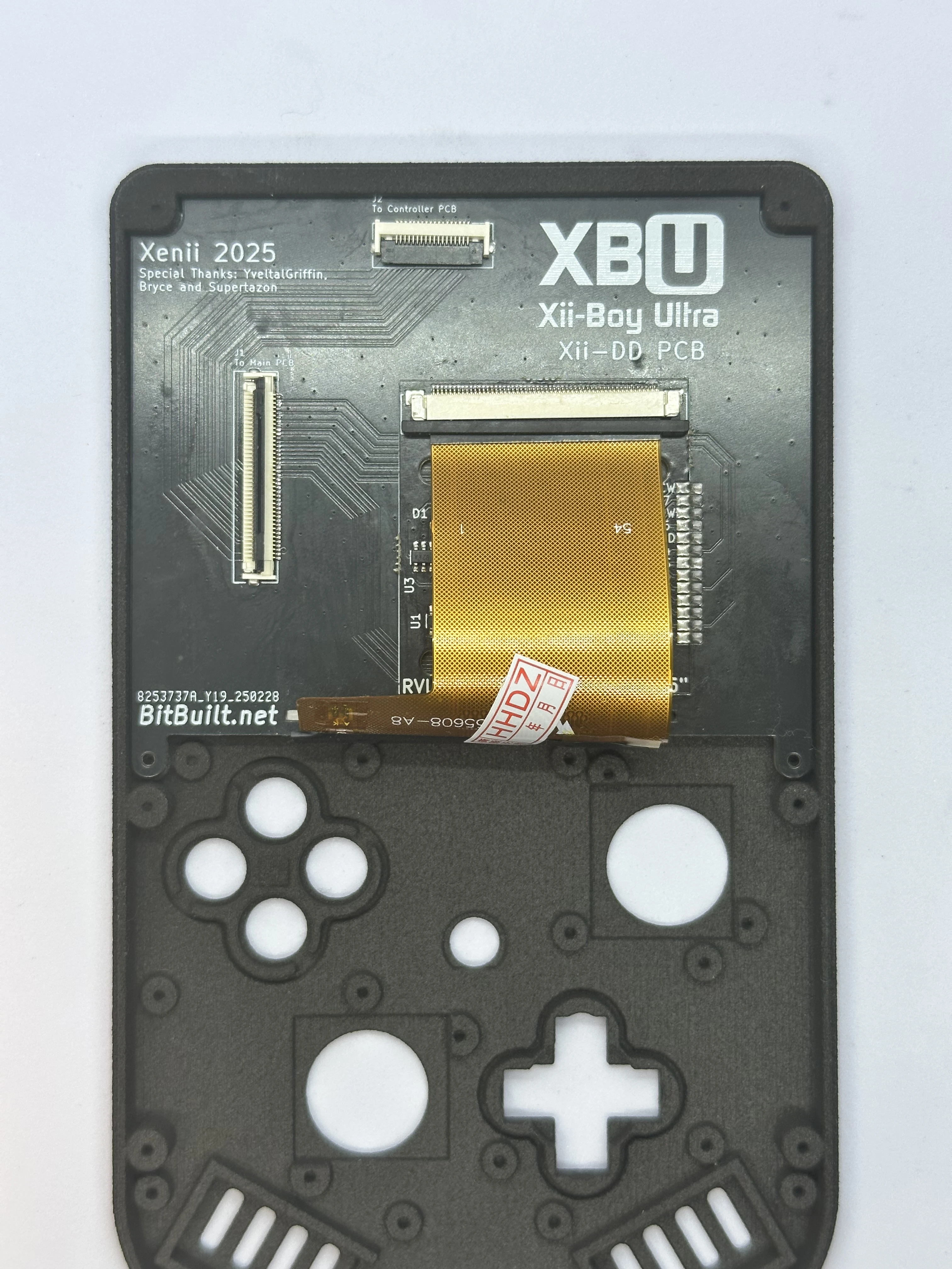
- Flip the top shell so the external side is facing down. Then, slide the Xii-DD PCB at a
20°angle on the back of the display until it pushes against the top of the shell and underneath the notch. Fasten the Xii-DD PCB in place using two4mmPhillips screws.
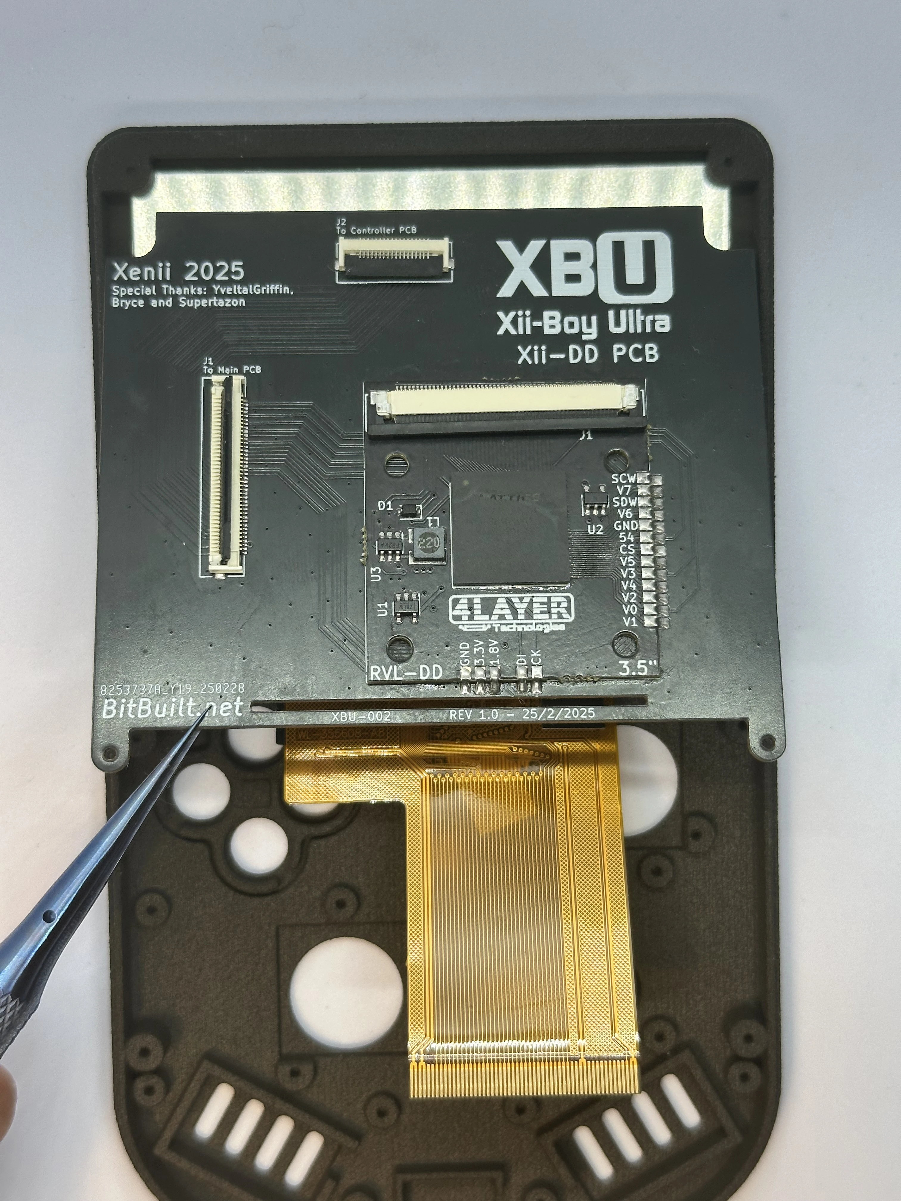
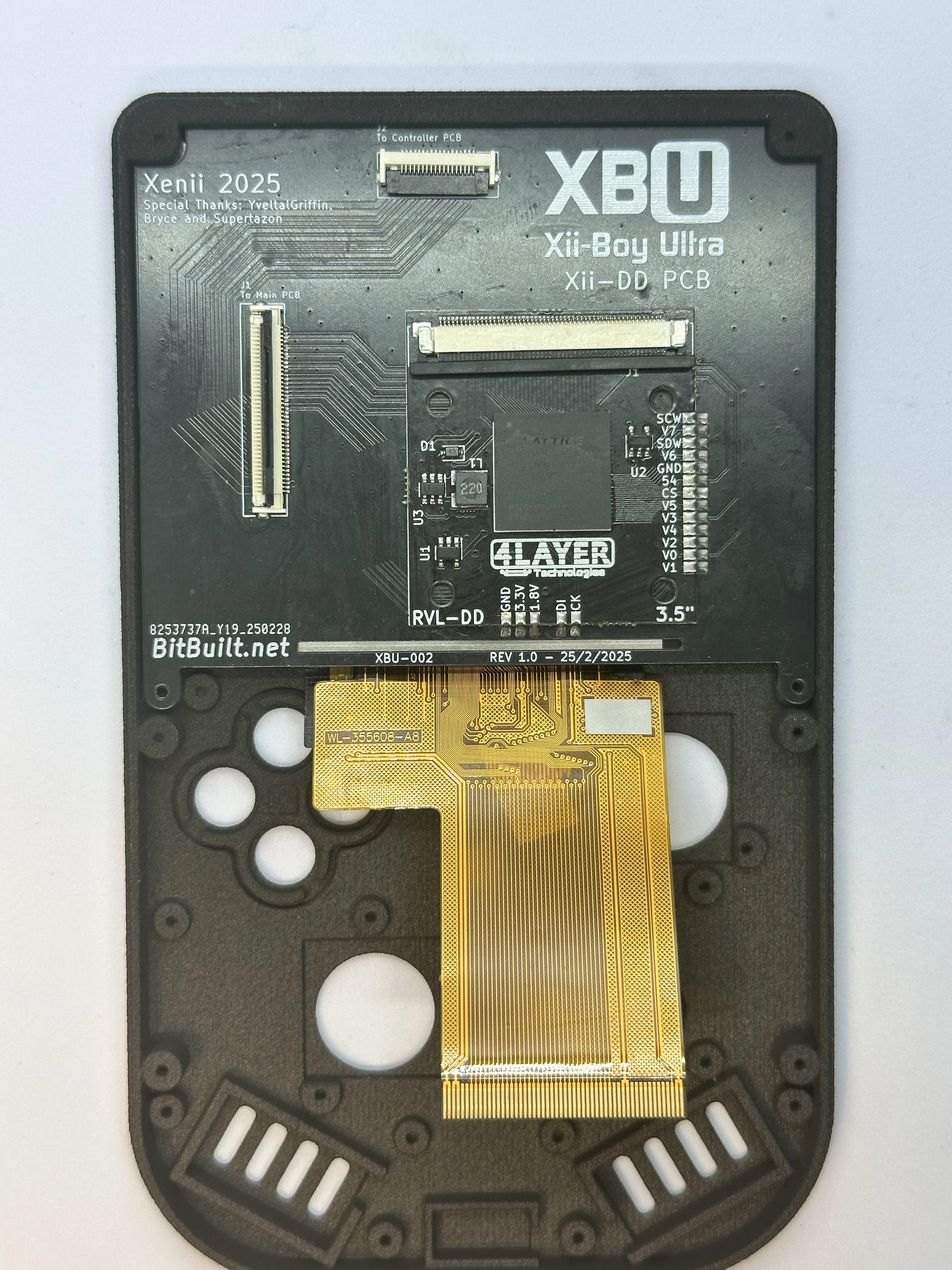
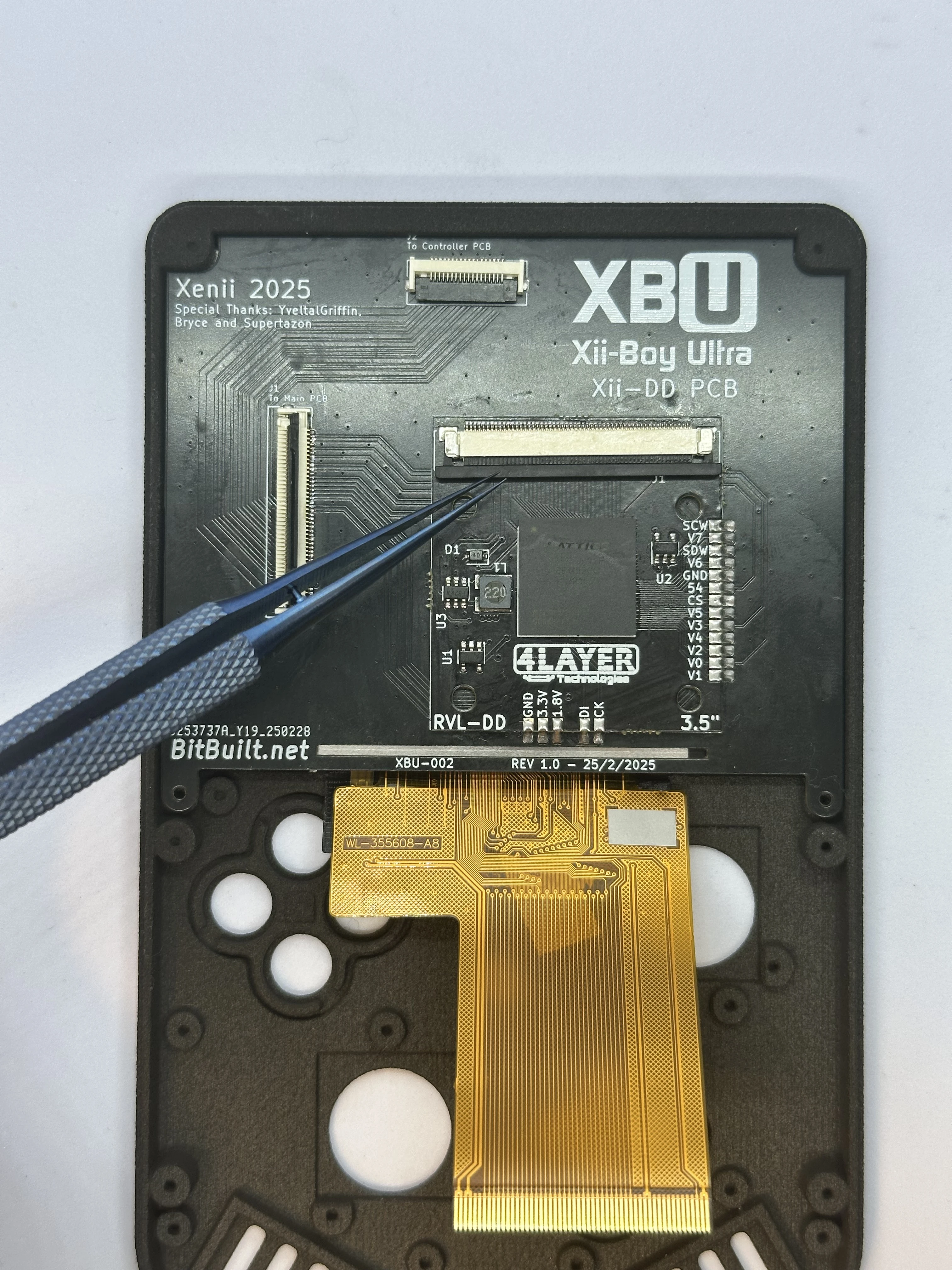
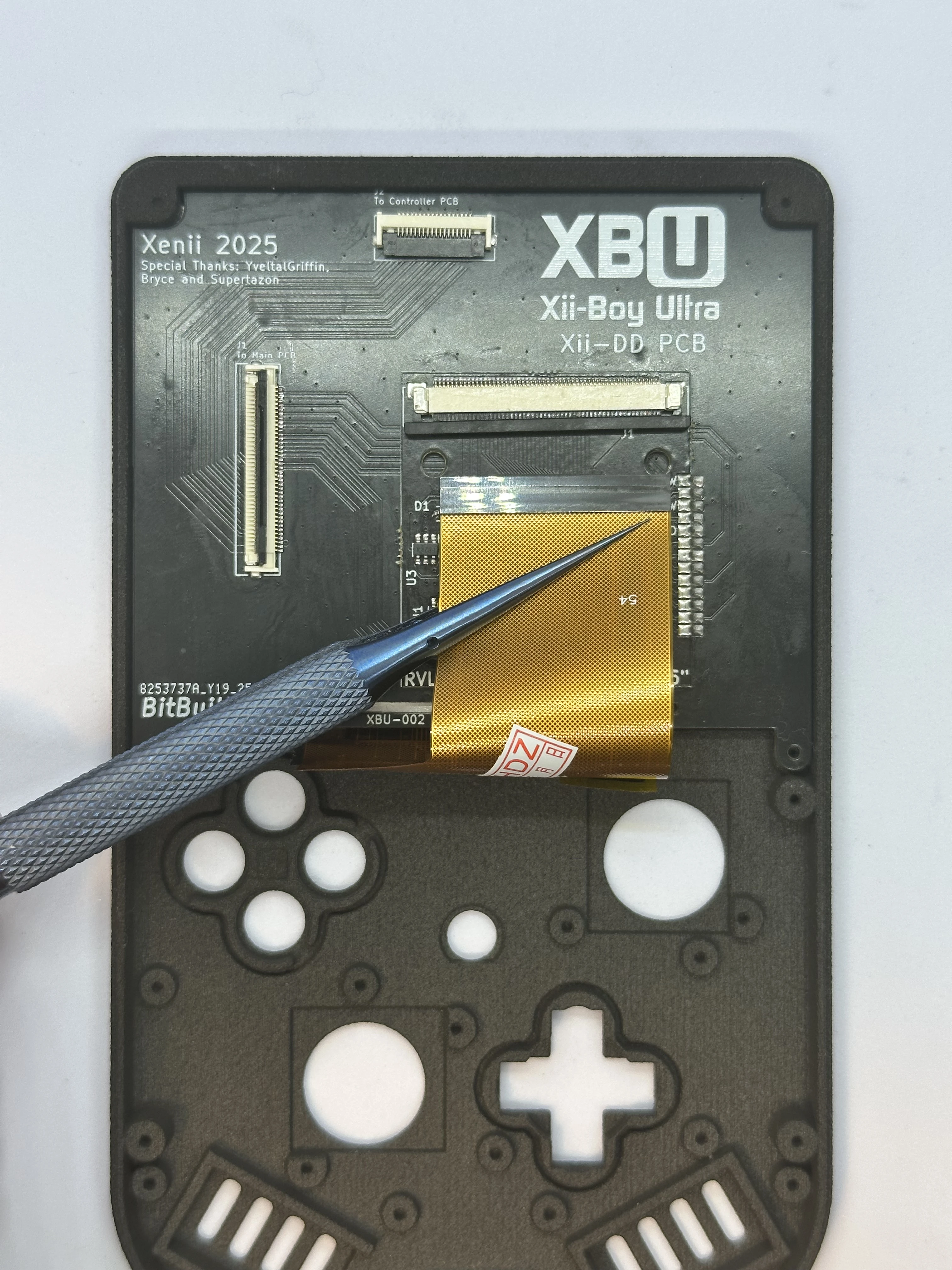
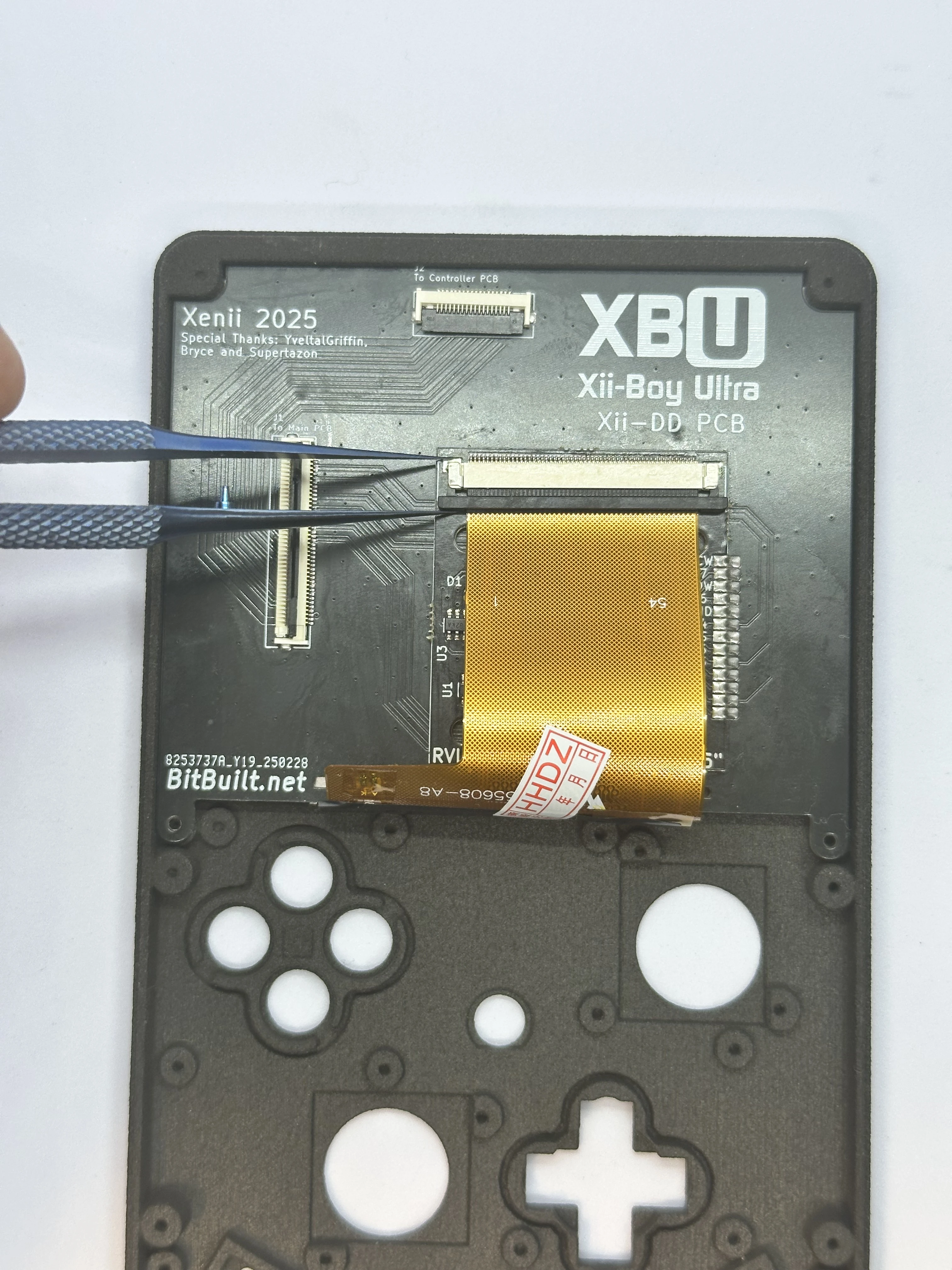
Open the slider ZIF connector on the RVL-DD. This ZIF is different from all others used in the XBU. To unlock it, pull directly away from the connector on both sides using a small amount of force. Do NOT pull up on it at all. The connector is fully unlocked when it extends out
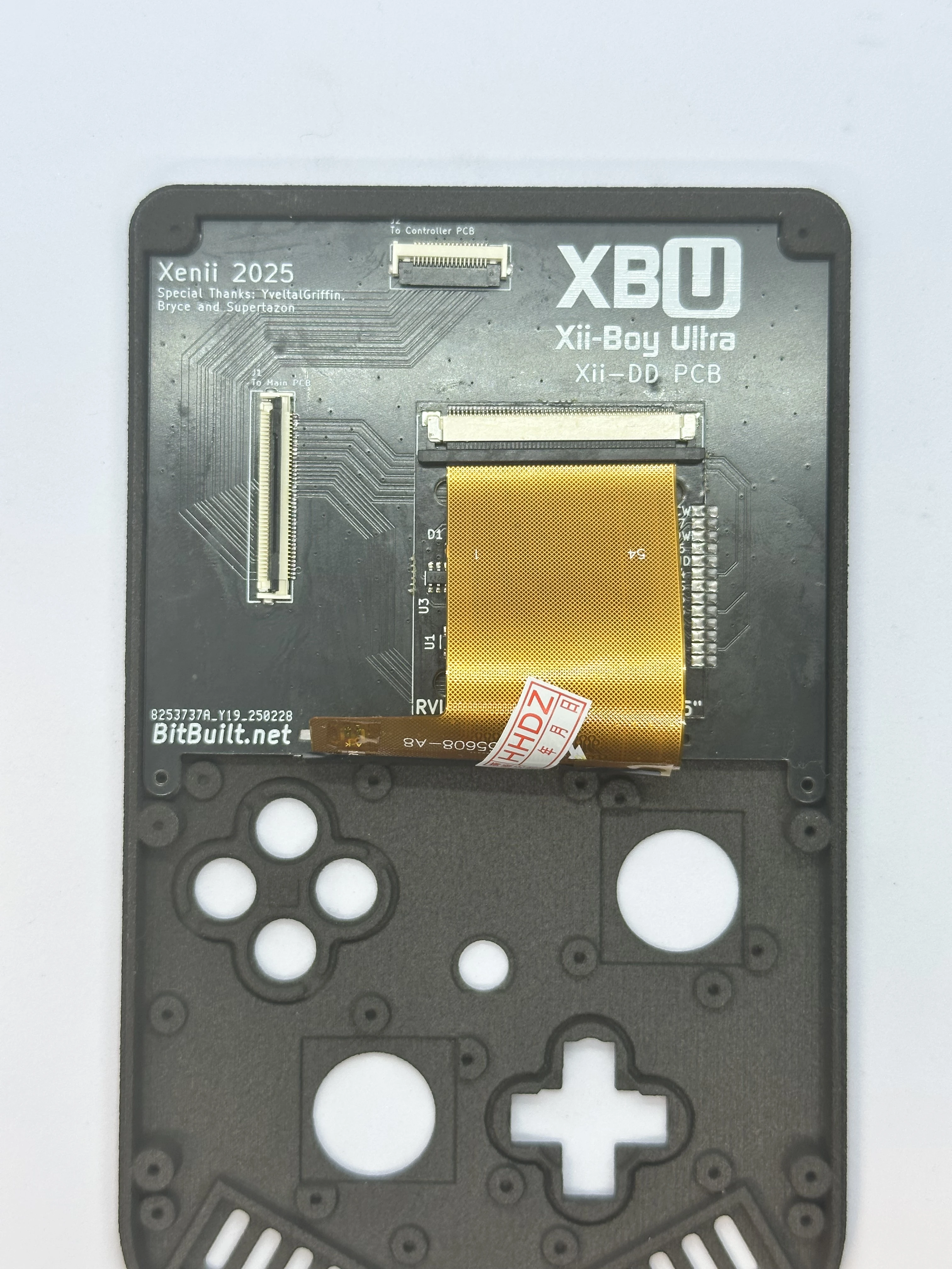
1-2mmand is even across both sides.Fold the 3.5" display’s cable over the bottom edge of the Xii-DD PCB. Align it properly and carefully push the cable into the unlocked ZIF connector. Ensure it is pushed in all the way, as it can get stuck easily. Then, lock the ZIF connector.
Face Buttons
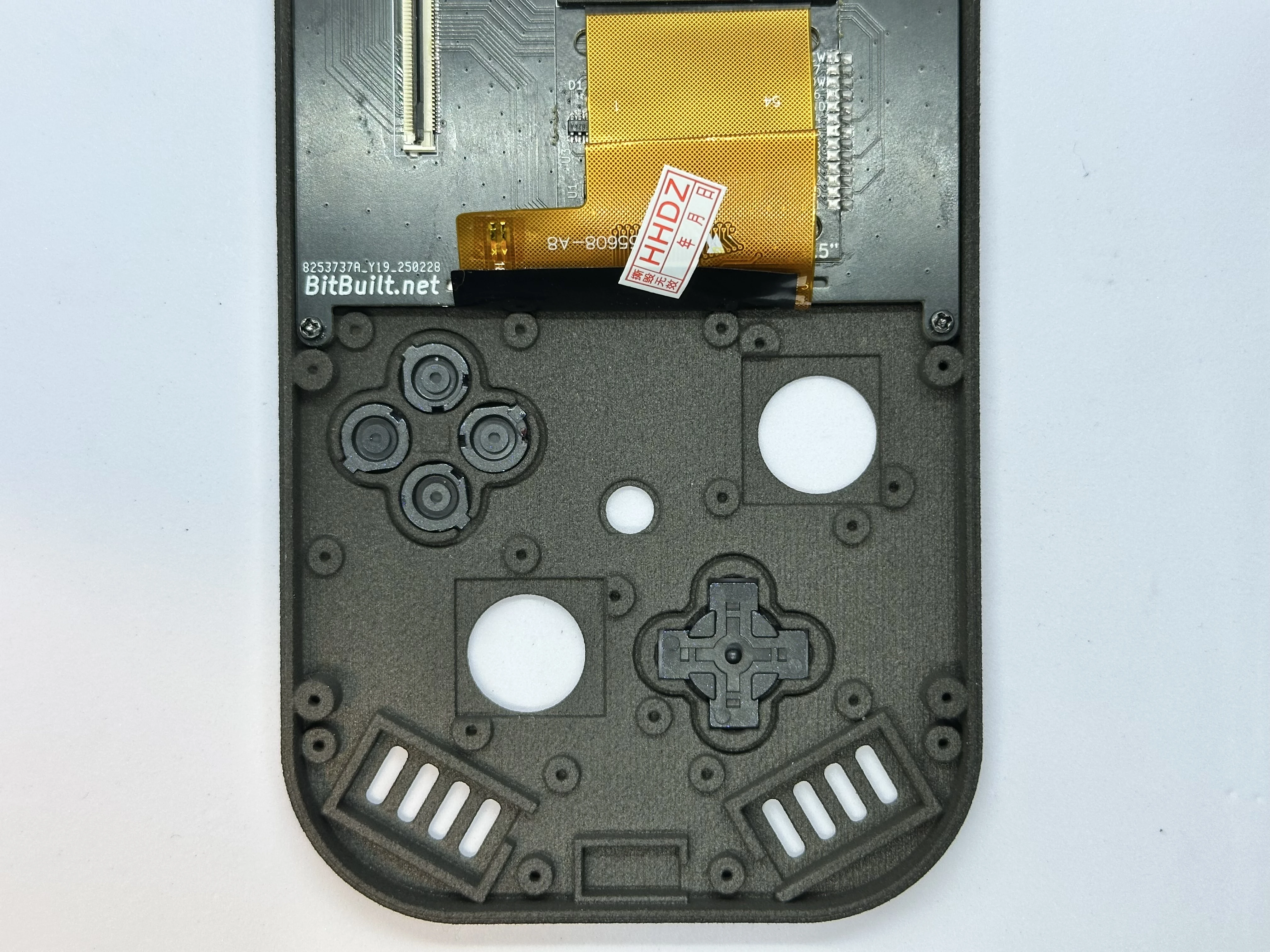
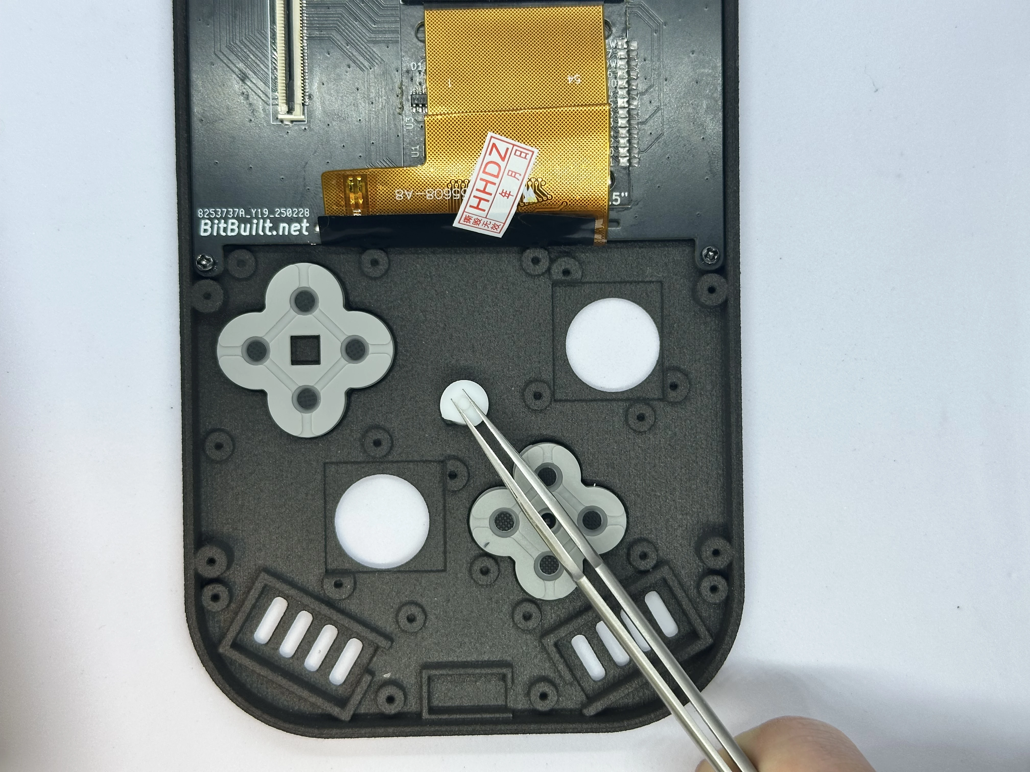
- Place the DS lite buttons and D-pad in their respective slots. The buttons have notches to ensure correct orientation. The D-pad, however, can be installed in any orientation.
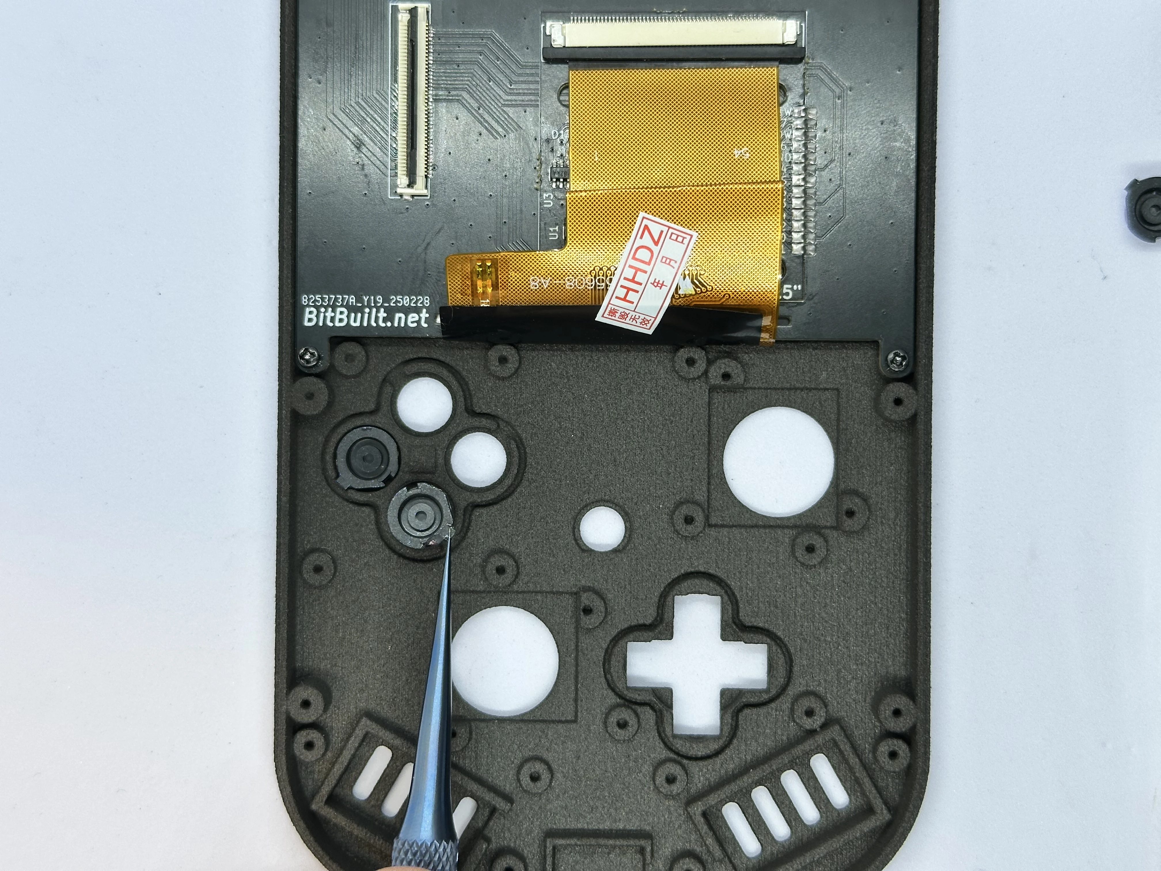
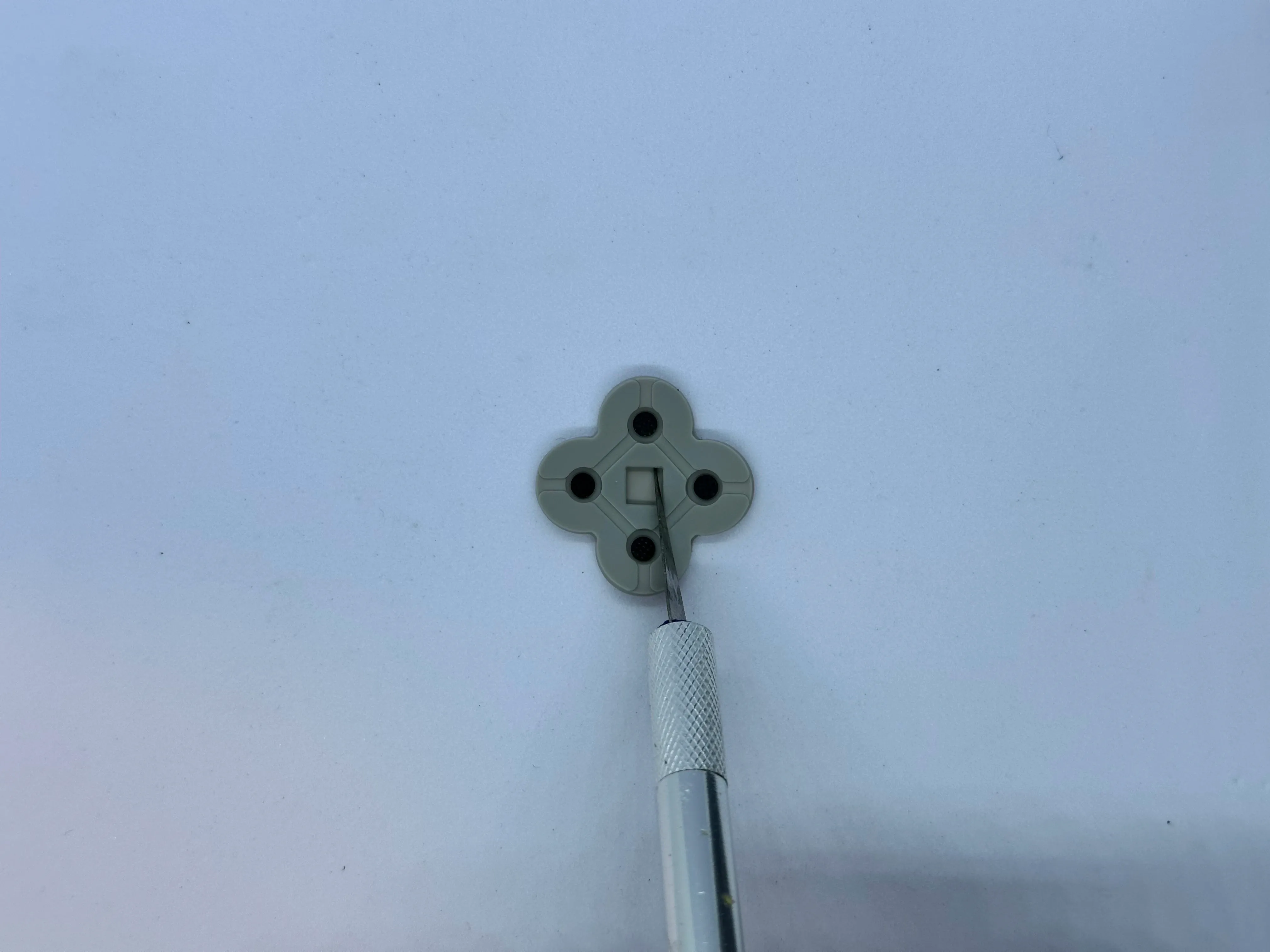
- Trim the membrane for the buttons. This is a required step - it is done to create a tighter fit with the shell. The square in the middle of the membrane can be completely cut out using an X-Acto knife with a
#2blade.
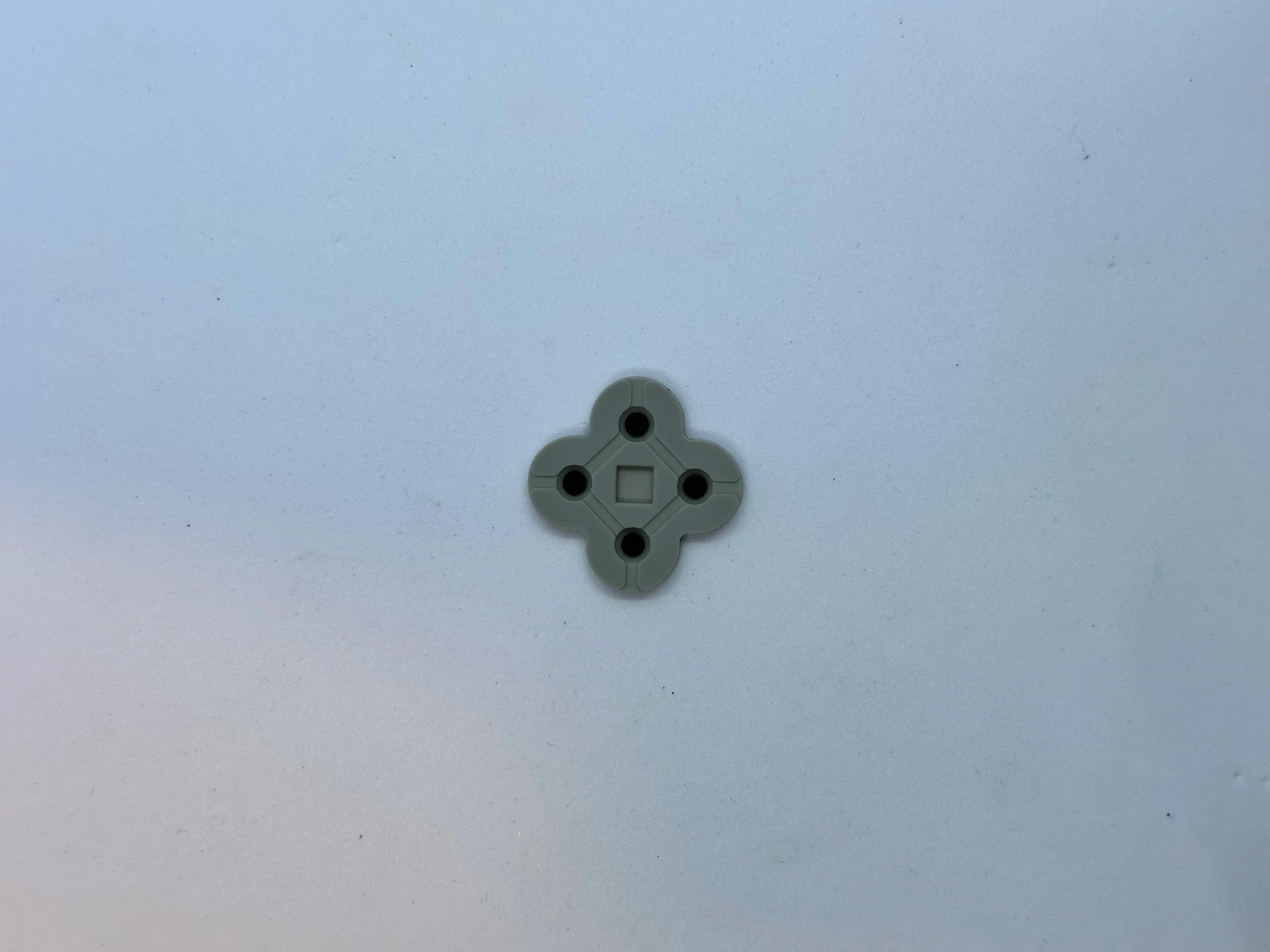
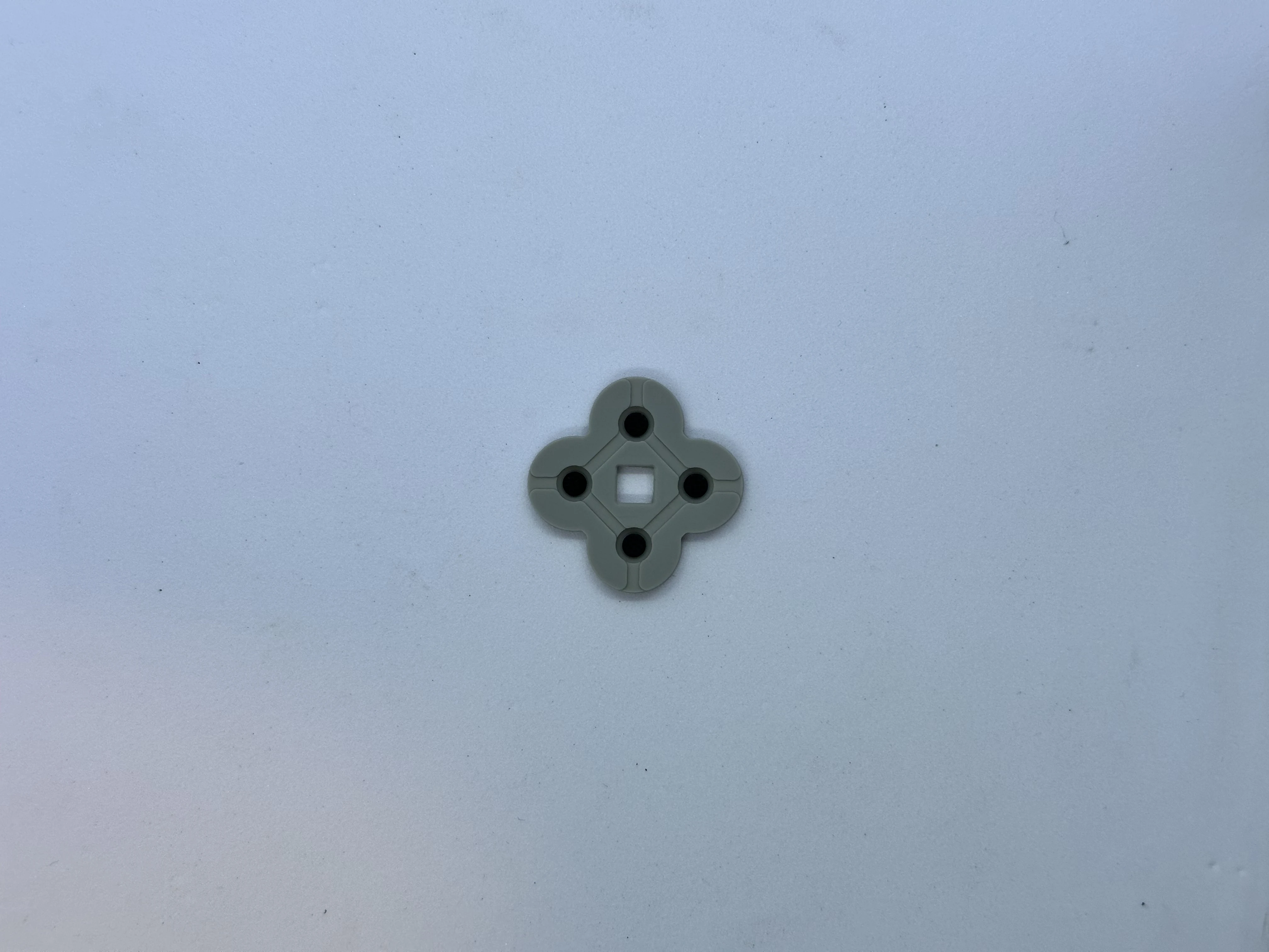
- Place the membranes for the buttons and D-pad. Then, place the center Start button. If the button's membrane does not sit flat, consider trimming the square a bit wider.
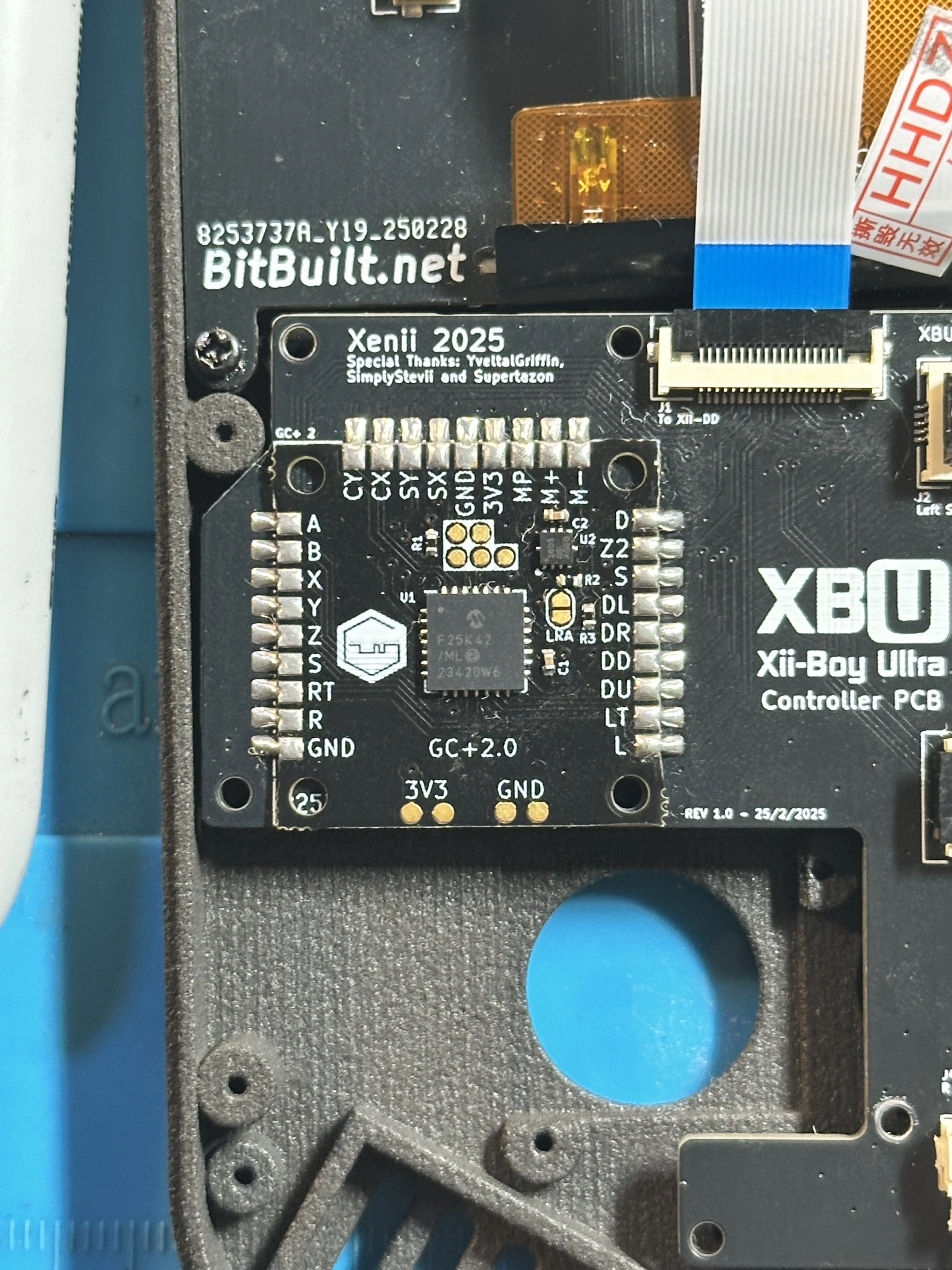
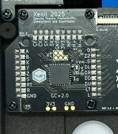
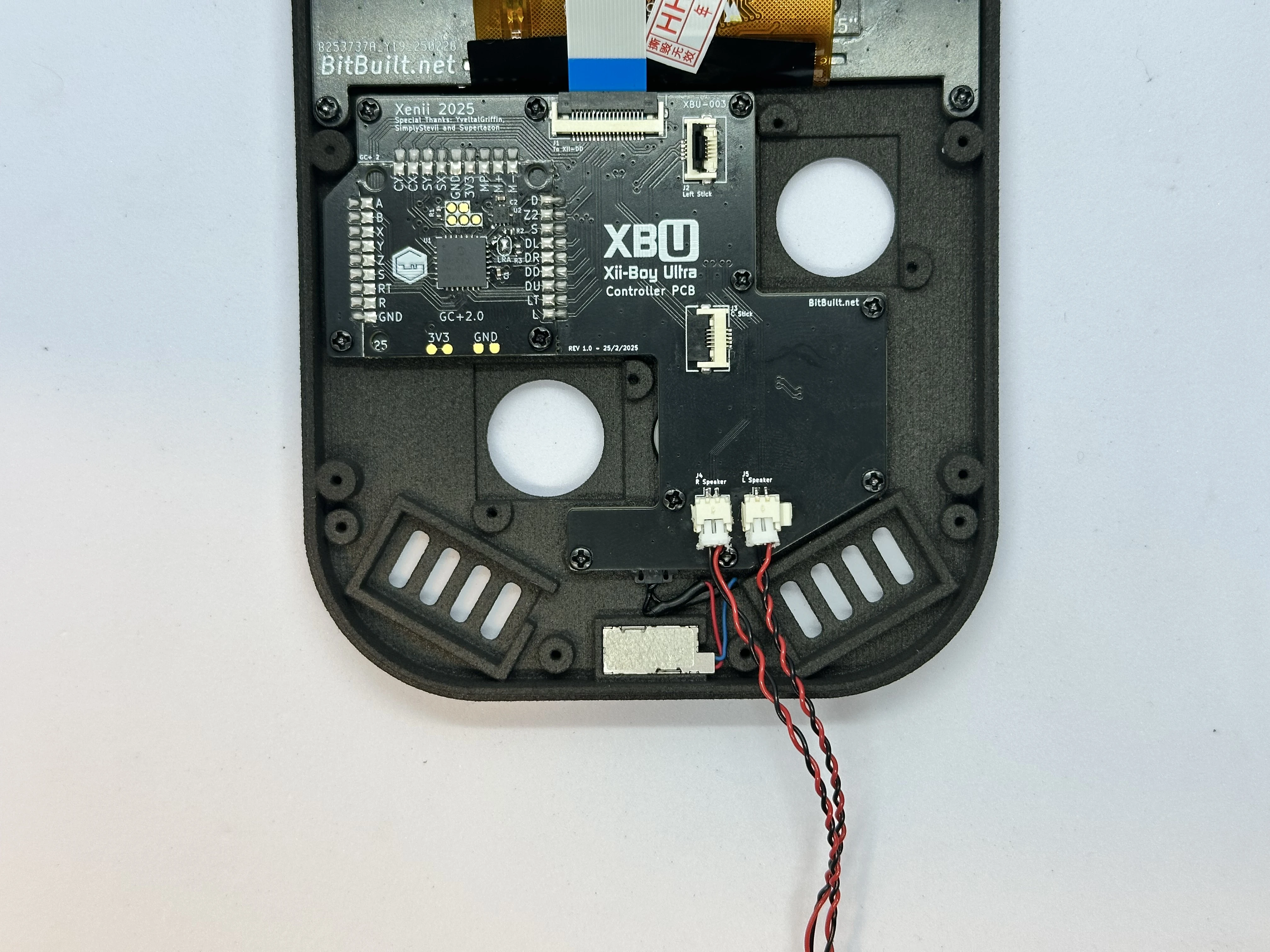
Controller PCB (XBU-003)
Note
The order of the following steps is not optimal and needs to be updated. Use as reference only.
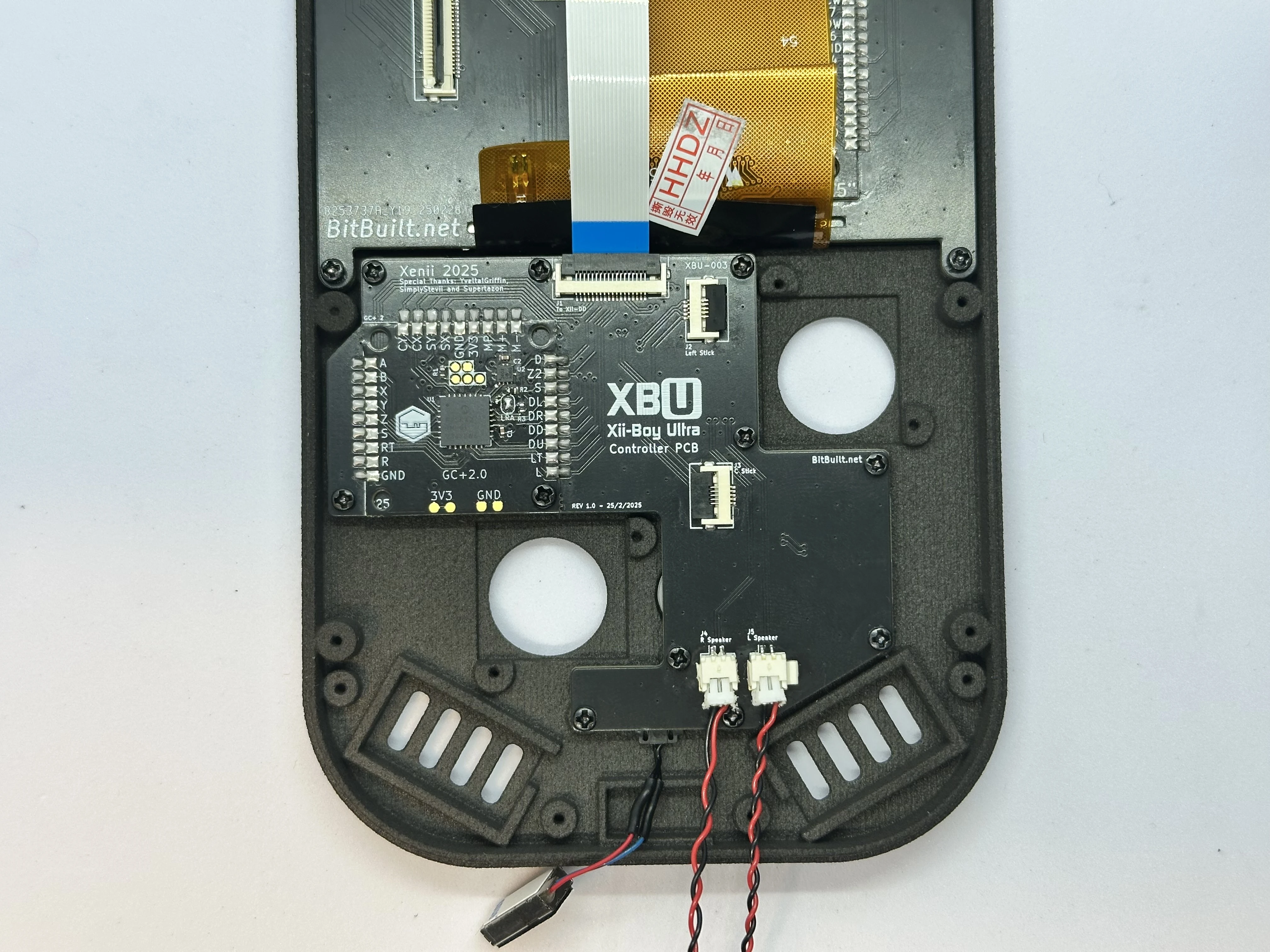
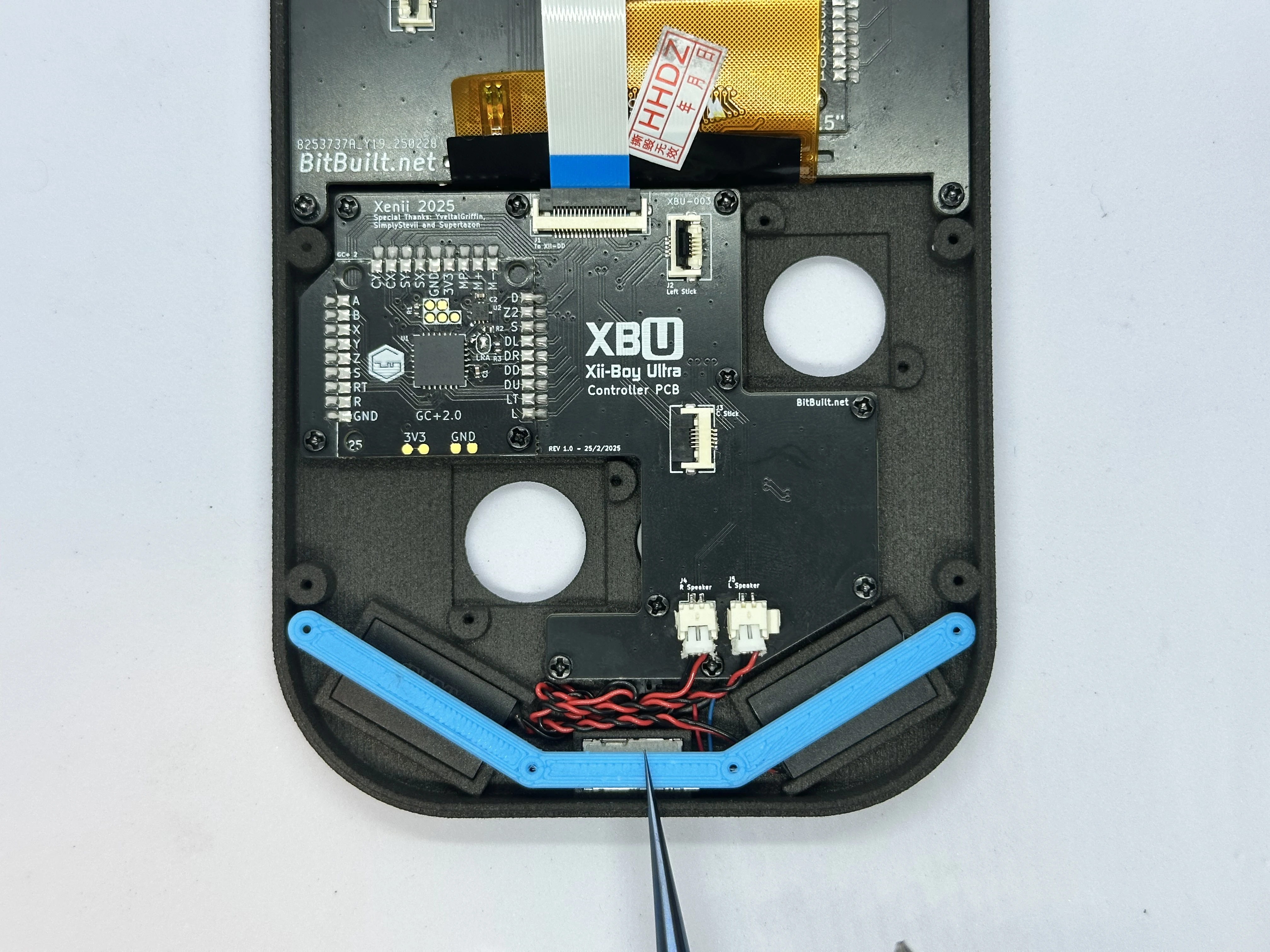
- Take the Left and Right Speakers and connect them at the bottom of the PCB. They push directly in and will stay snug there.
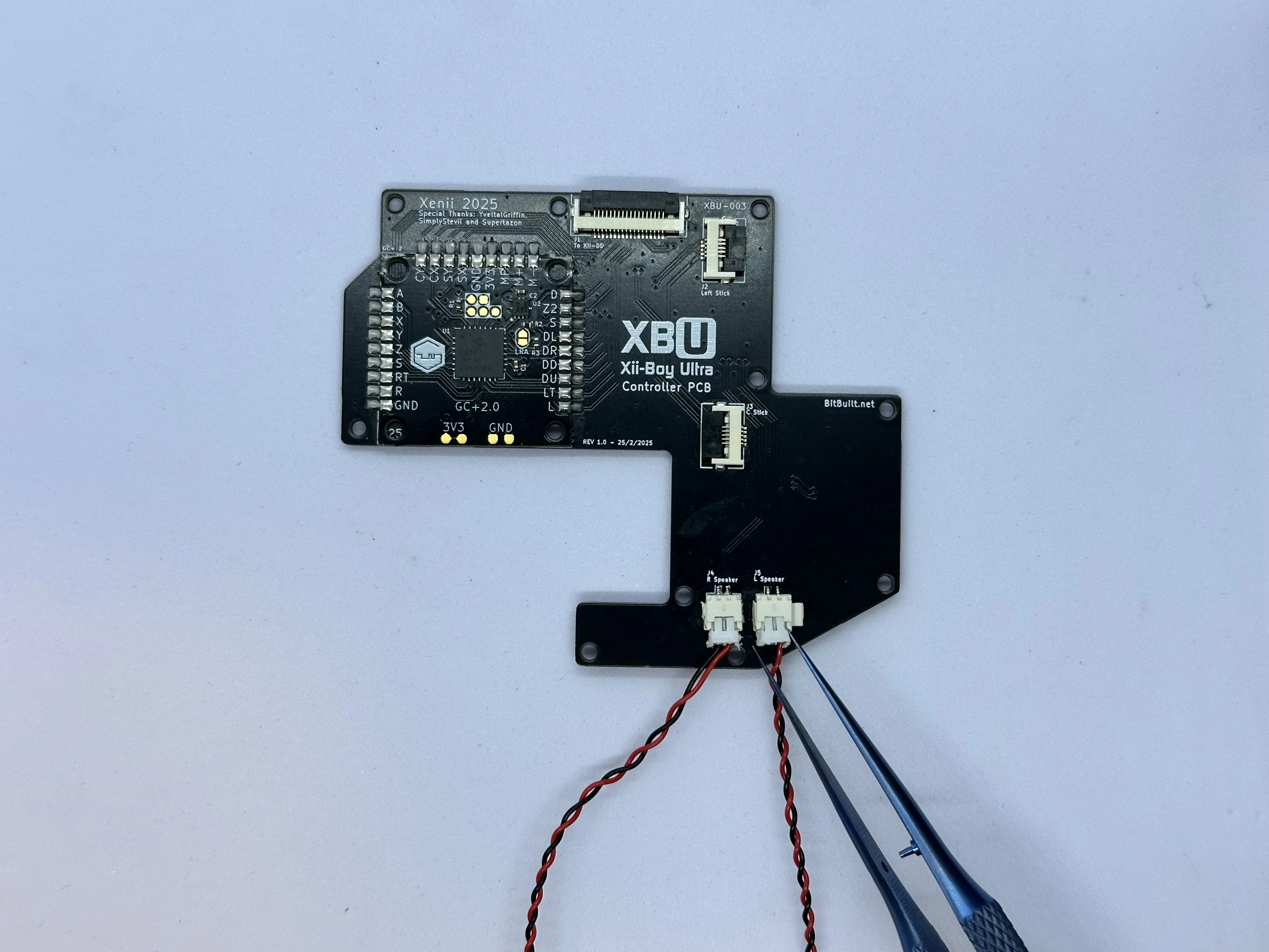
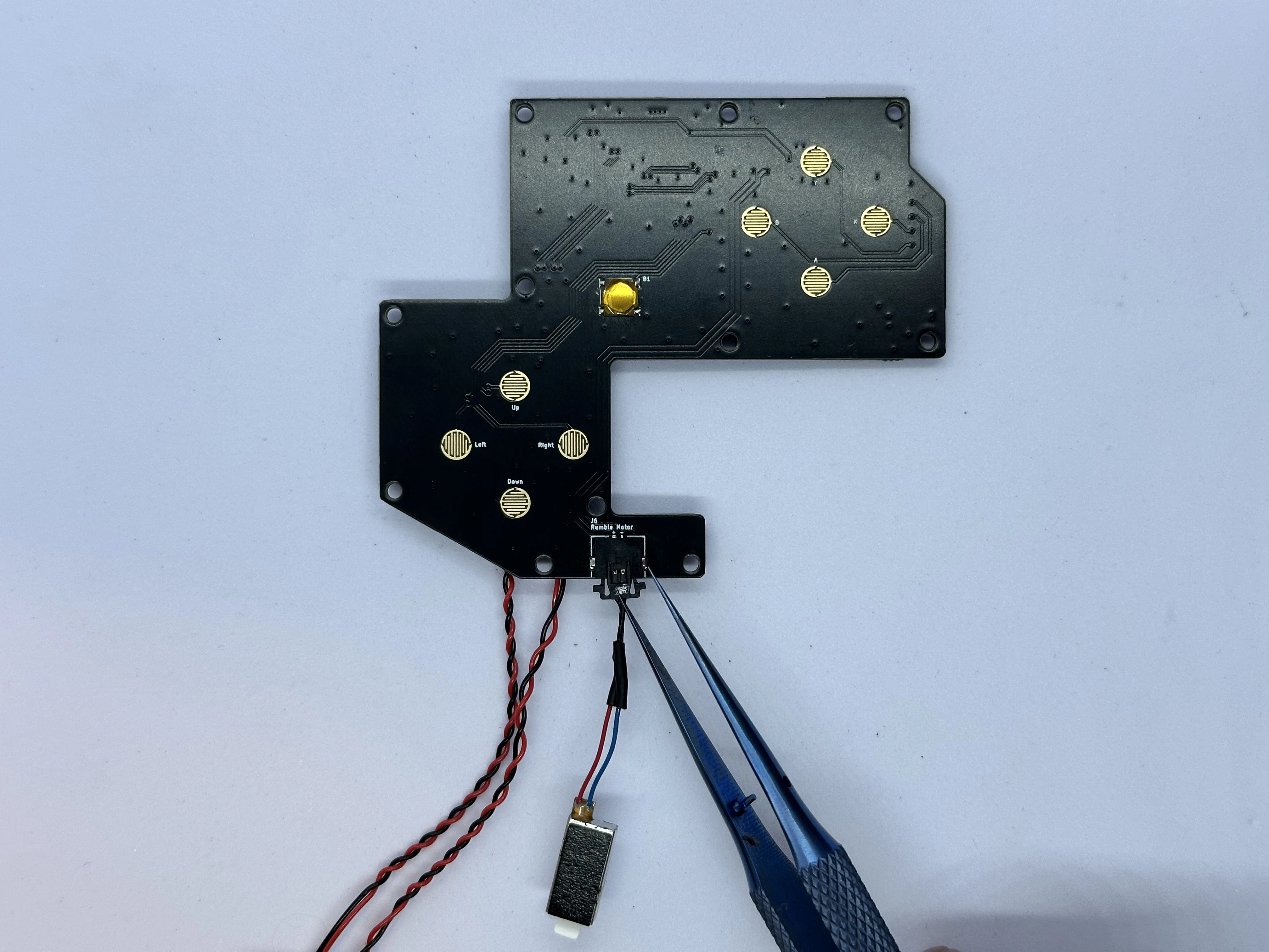
- Connect the rumble motor to the picolock connector at the bottom of the Controller PCB. The picolock connector is keyed and will only insert in one direction. Do not force it. Take note of the polarity: The red wire on the rumble motor connects to the
+pad, and the blue to the-pad.
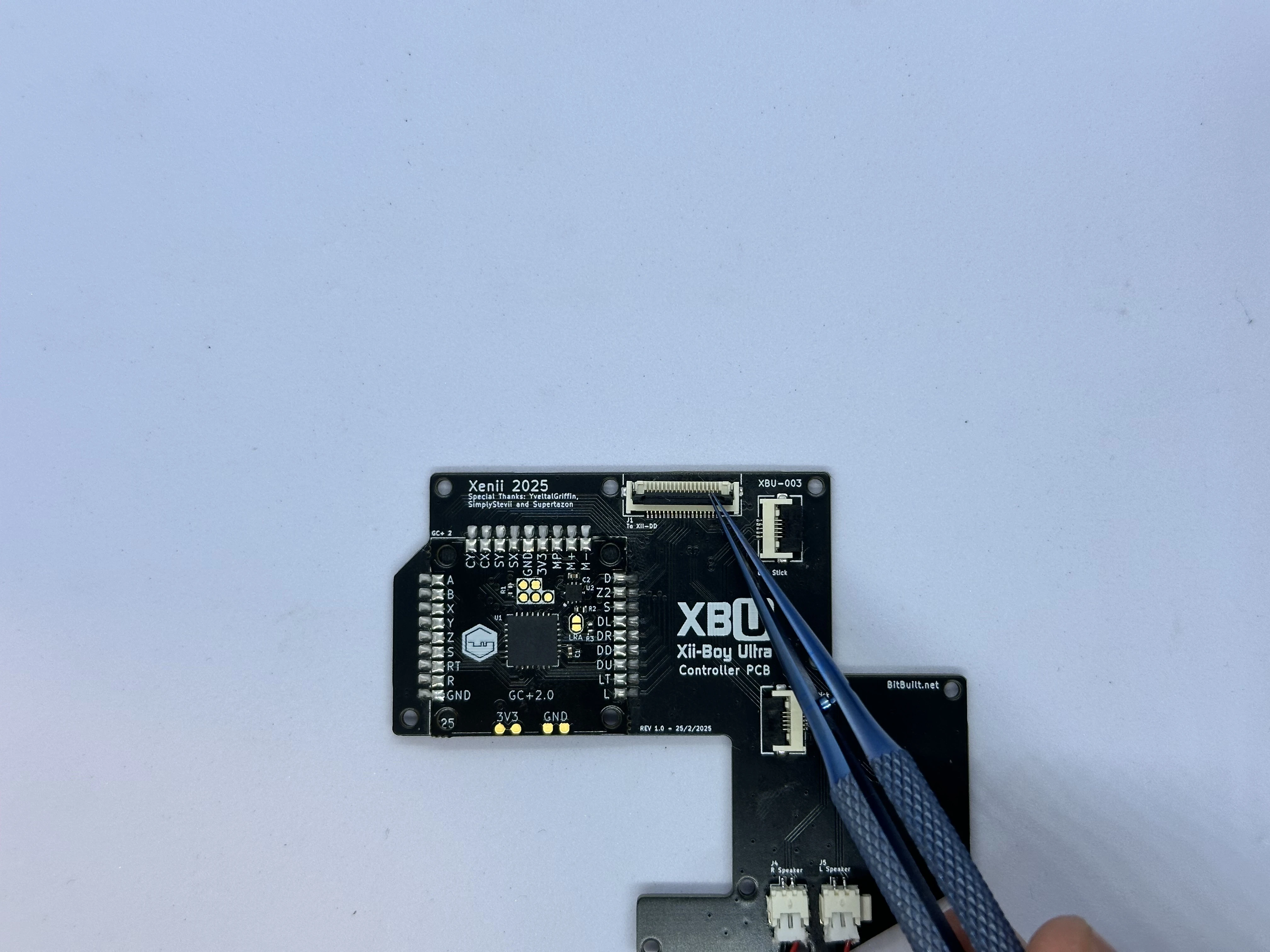
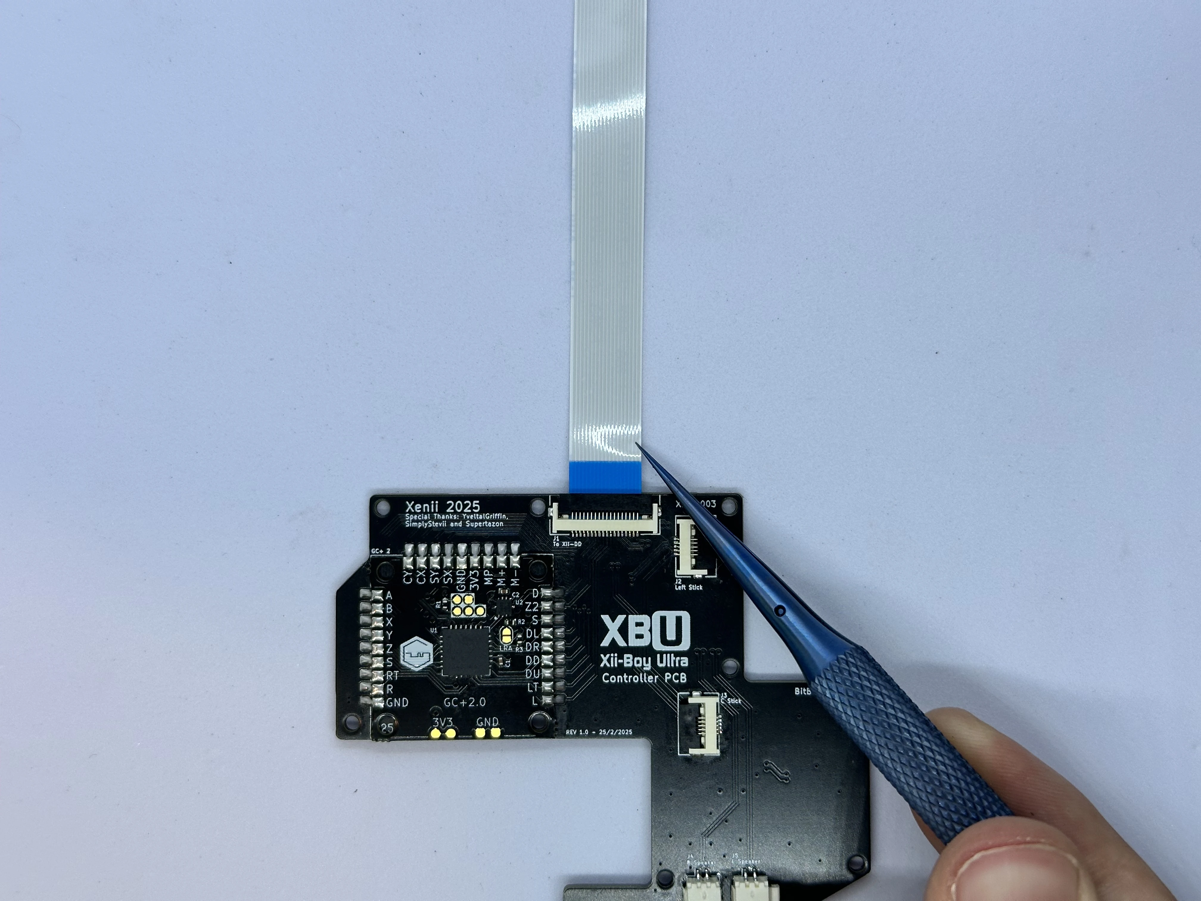
- Unlock the ZIF connector on the Controller PCB labeled
To Xii-DD. Insert an 18 pin FFC with the blue stiffener facing up. Then, lock the connector.
- Apply a small amount of flux to the
LRApads on the GC+2.0 PCB. Then, jump the two pads together by creating a solder bridge. Be careful not to damage any surrounding components.
Finishing Top Half
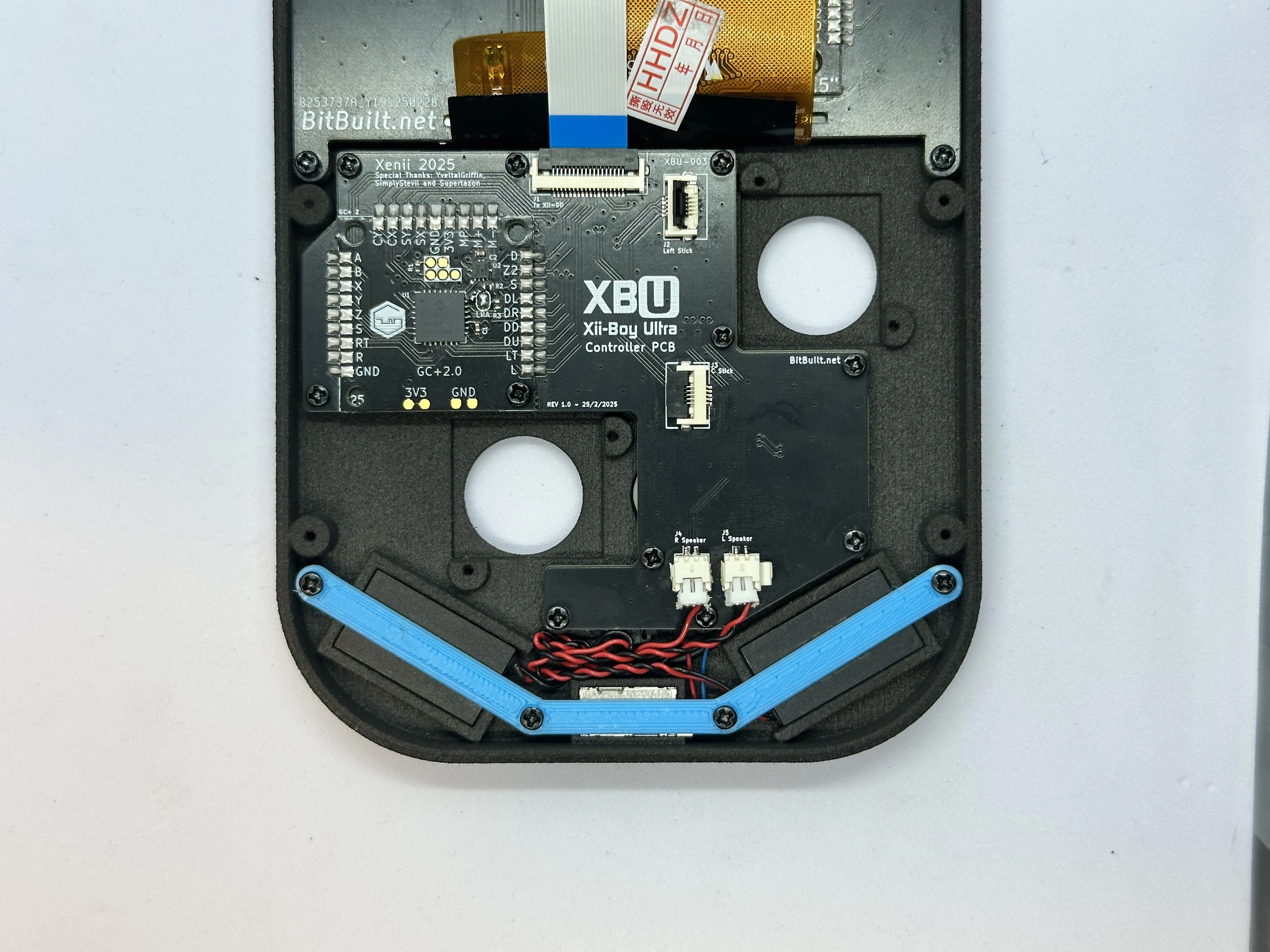
- Line up the completed Controller PCB with its screw posts. Ensure the cables for the rumble motor and speakers do not get caught underneath the PCB. Then, screw the board into place using eleven
4mmPhillips screws.
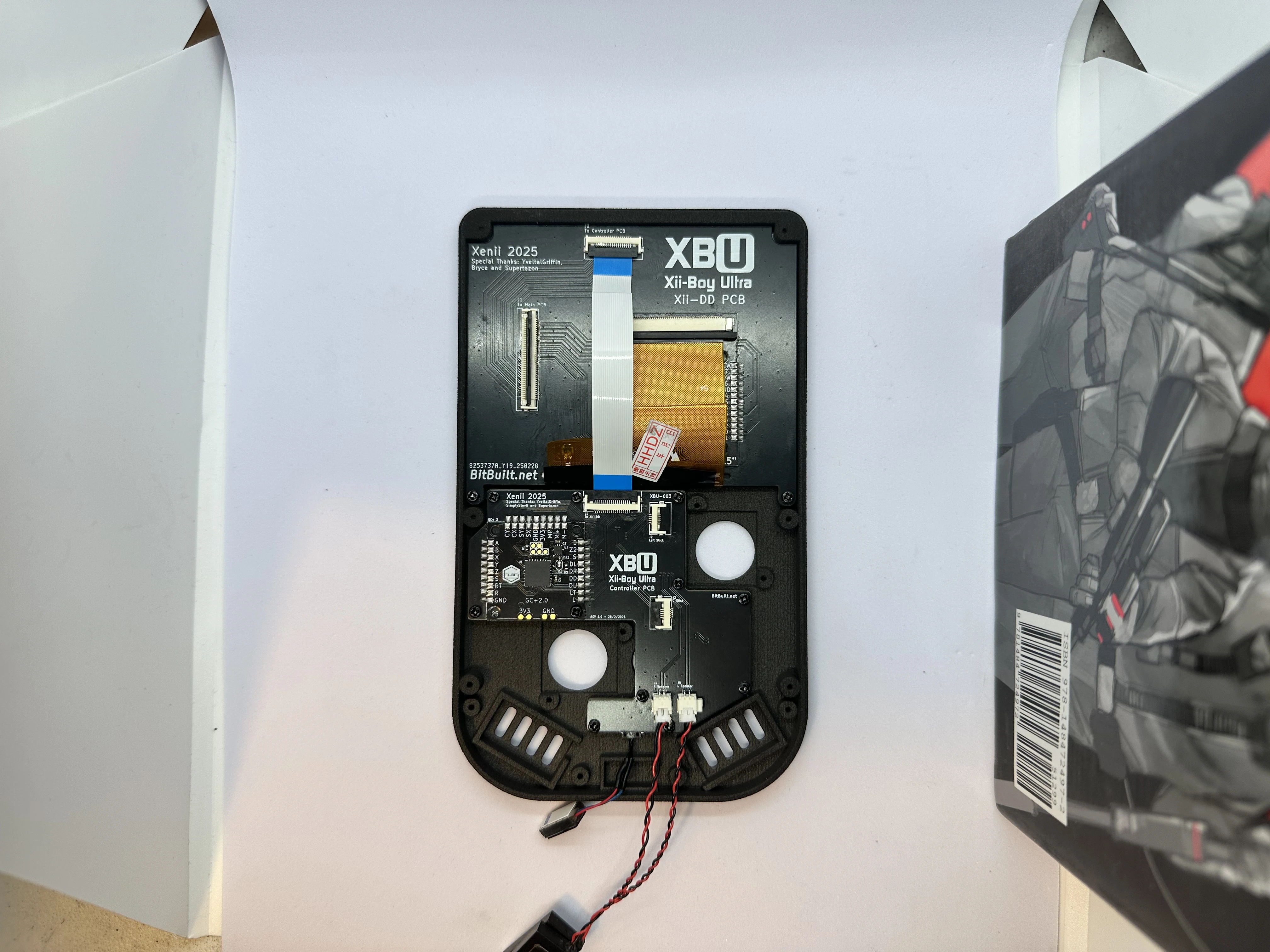
- On the Xii-DD PCB, unlock the 18 pin ZIF connector near the top and insert the FFC coming from the Controller PCB. Lock the ZIF connector when finished.
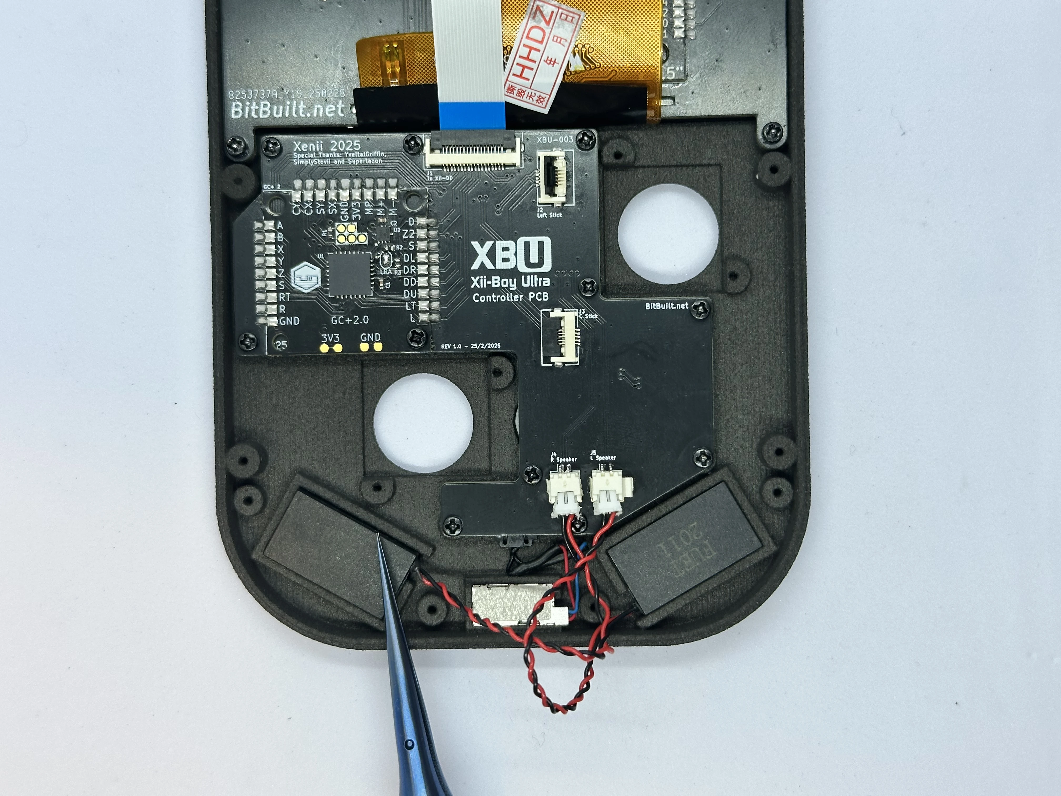
- Remove the sticker covering the adhesive backing on the rumble motor. Then, set the motor into its slot and tuck the wires under the PCB.
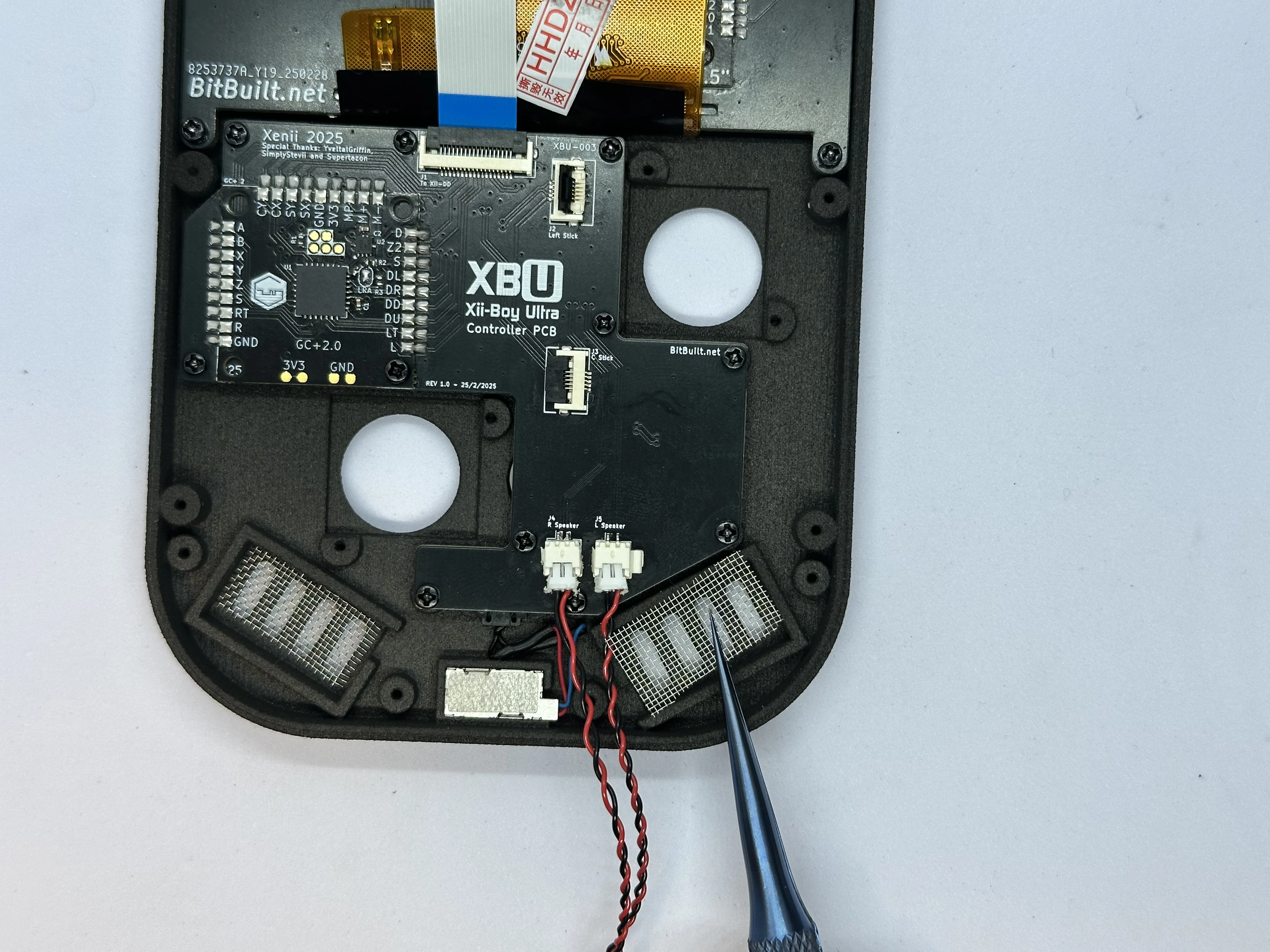
- Place a
19mm x 9mmspeaker mesh into each speaker cutout. After that, place each speaker in its slot, and tuck the excess wire in between the rumble slot and the PCB.
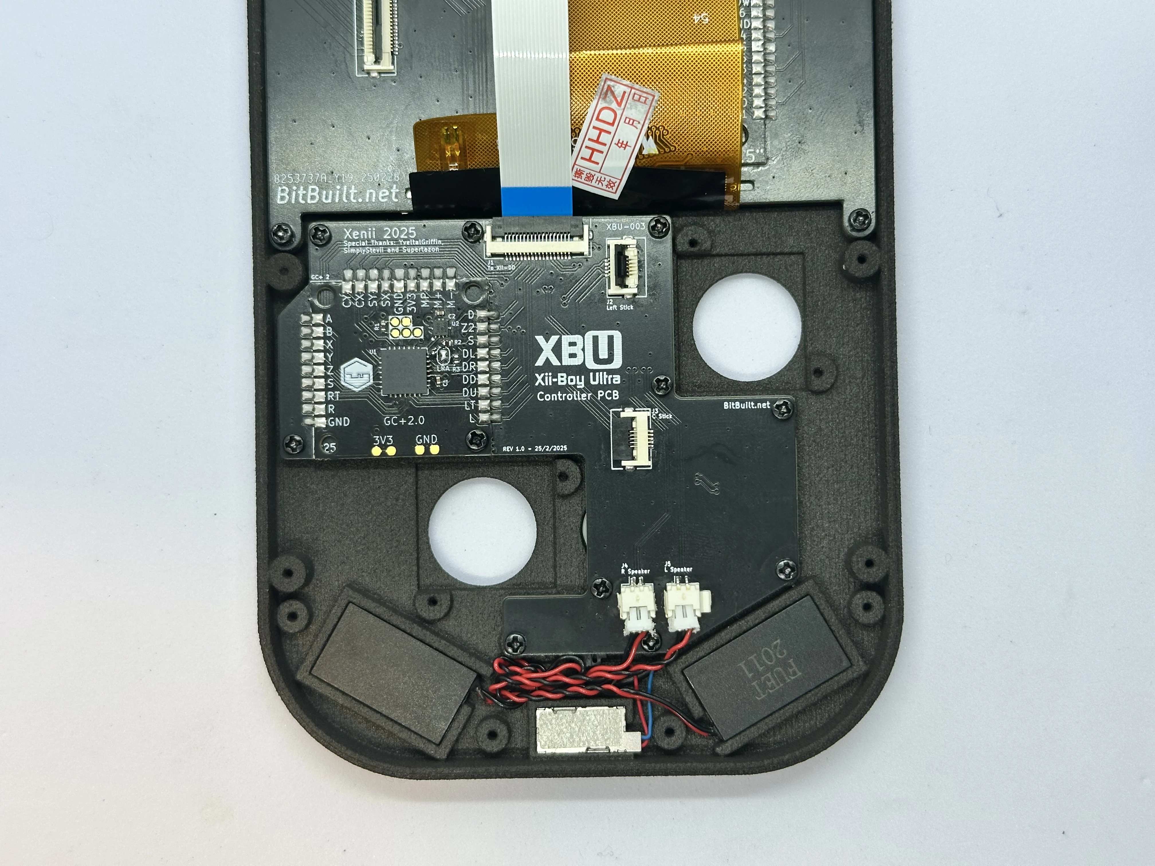
- Place the retention bracket over the speakers, rumble motor, and screw posts. Secure the bracket with four
4mmPhillips screws.
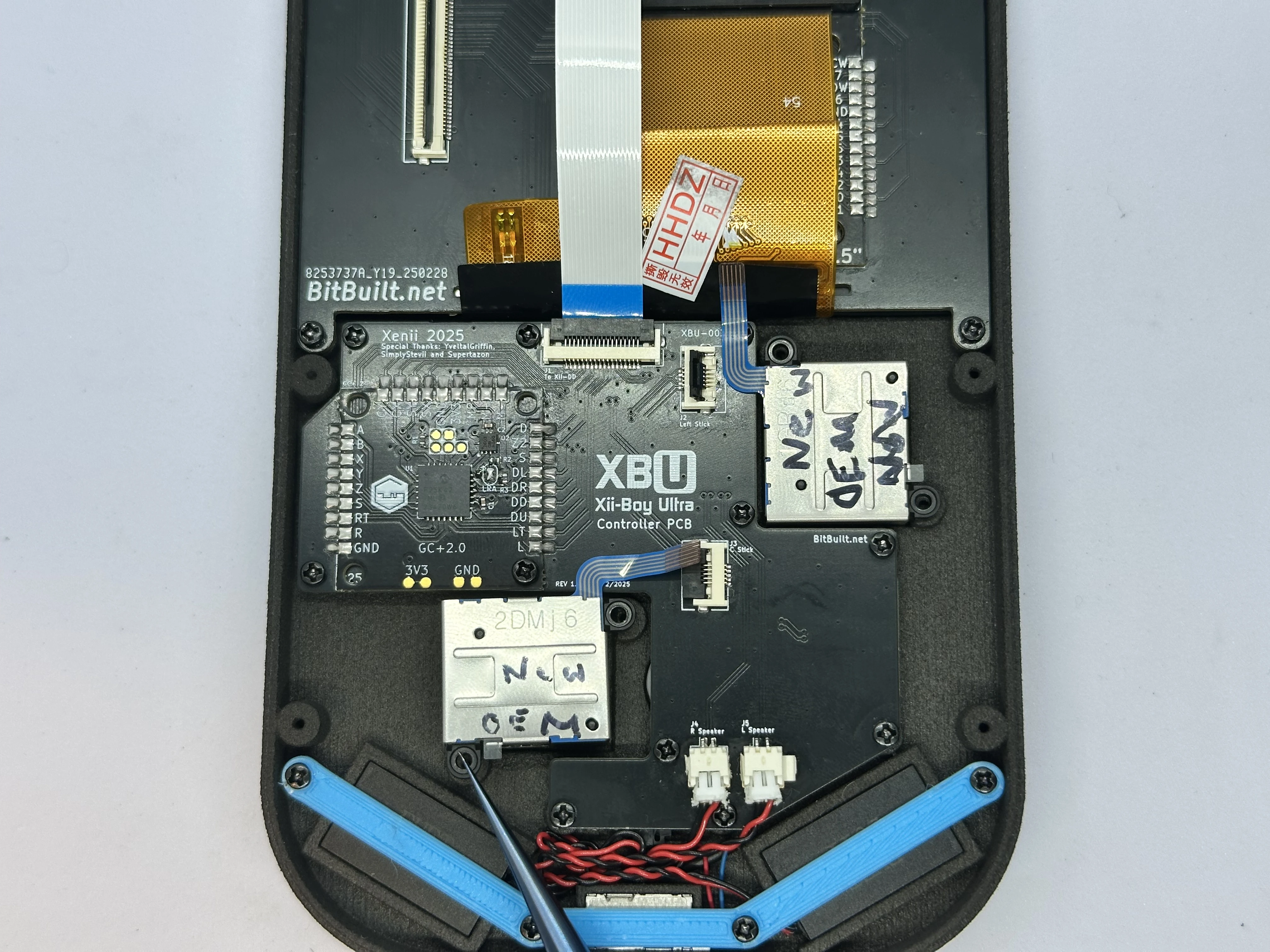
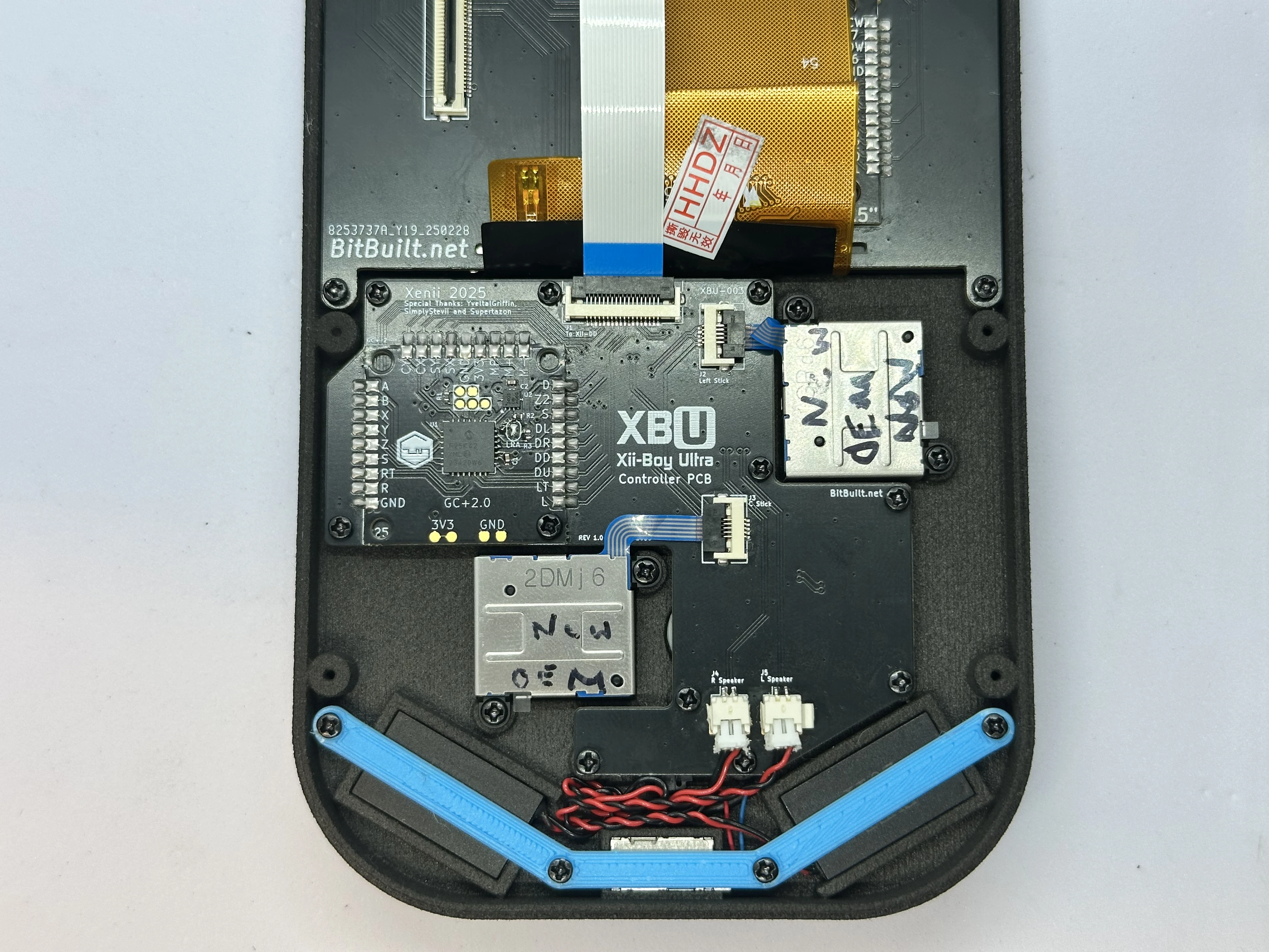
- Connect two Joy-Con Joysticks to their ZIF connectors. Then, place the joysticks over the screw posts and secure them with two
4mmPhillips screws each. The left joystick (closest to the RVL-DD) will need to have its cable folded in order to fit.
Bottom Half Assembly
Joystick Trigger Modification
Important
This trigger mod is only compatible with a specific revision of 3rd party joysticks. OEM and Hall sticks are not compatible and will not work. Use the included joysticks in the Xii-Boy Ultra Kit.
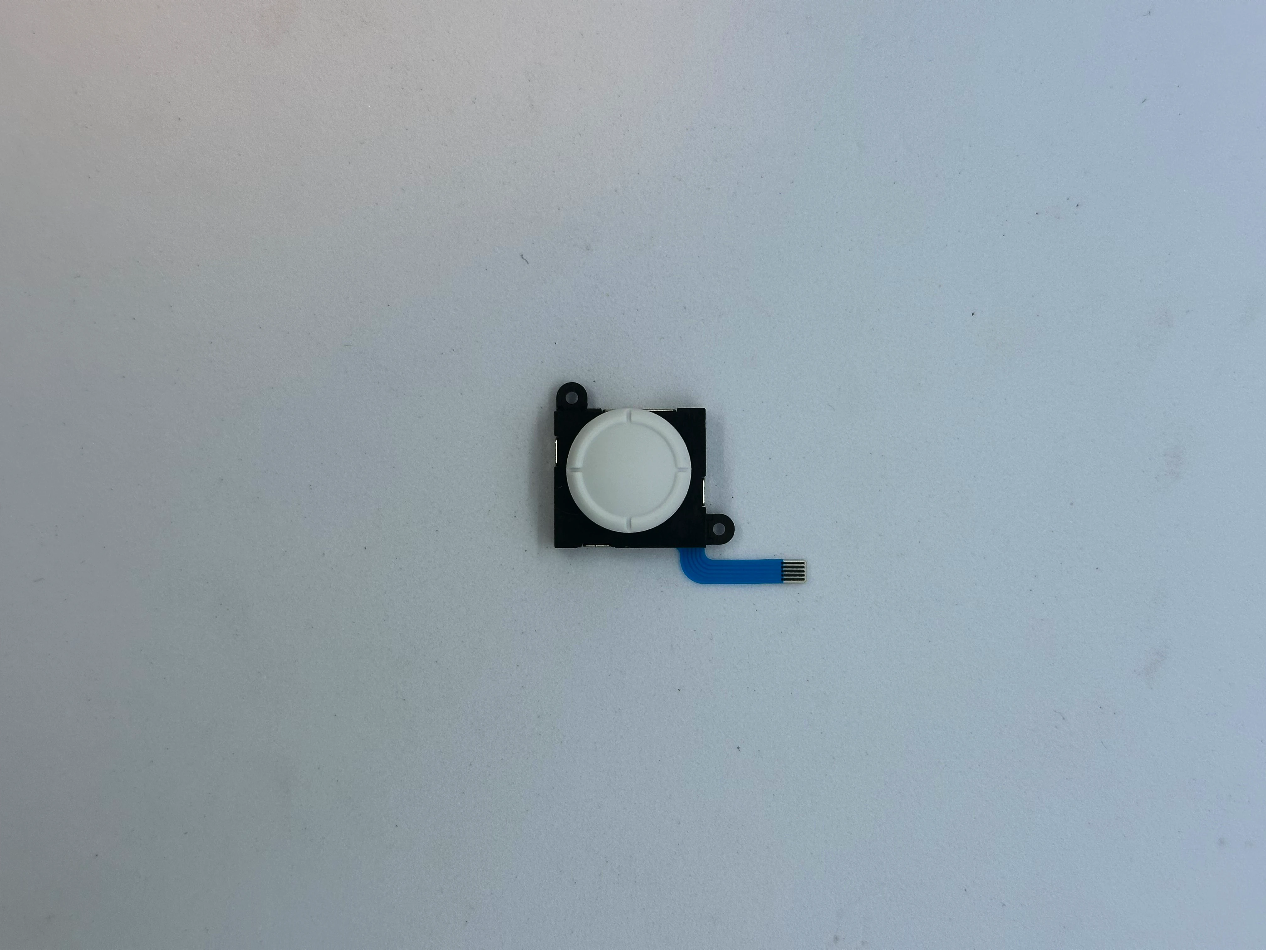
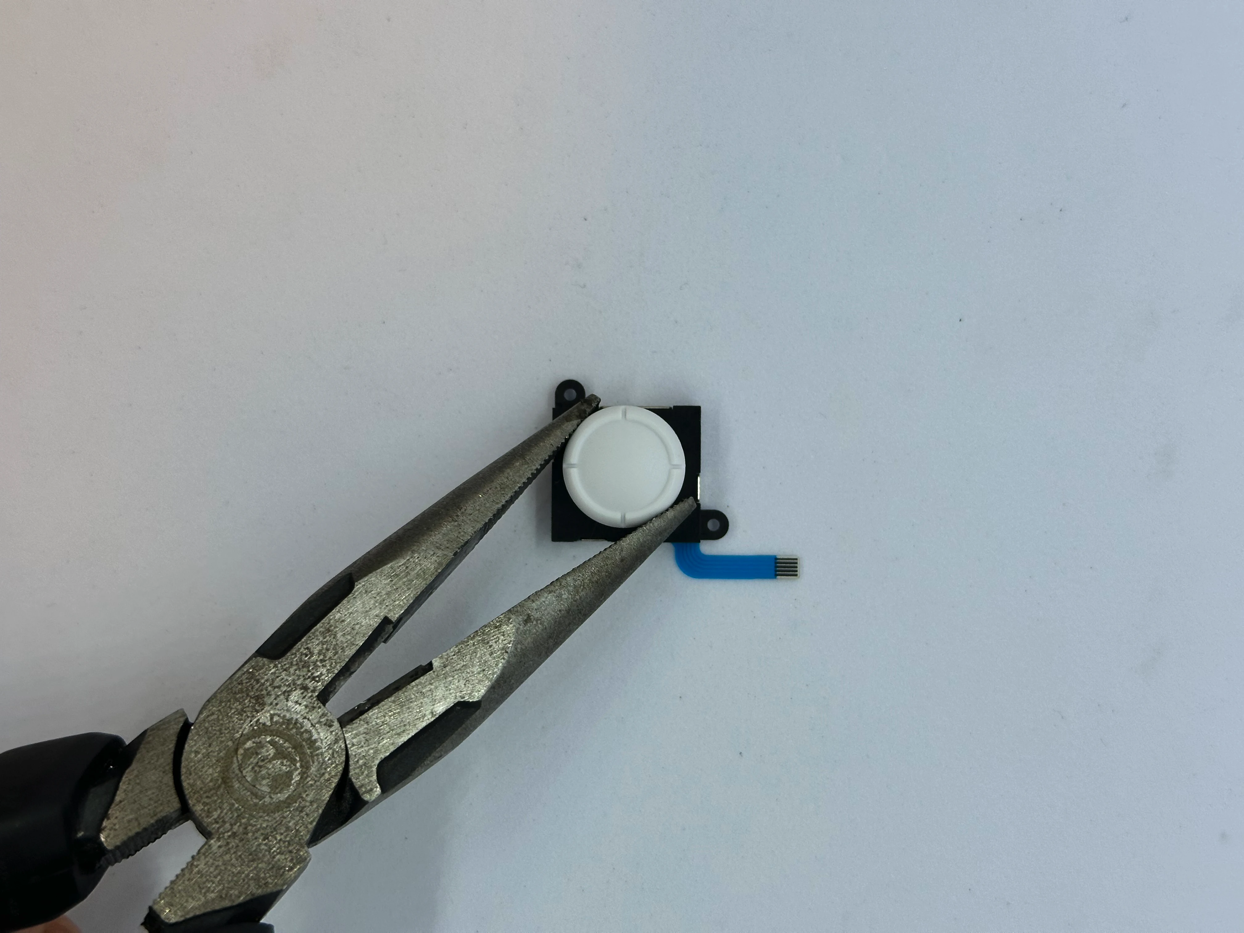
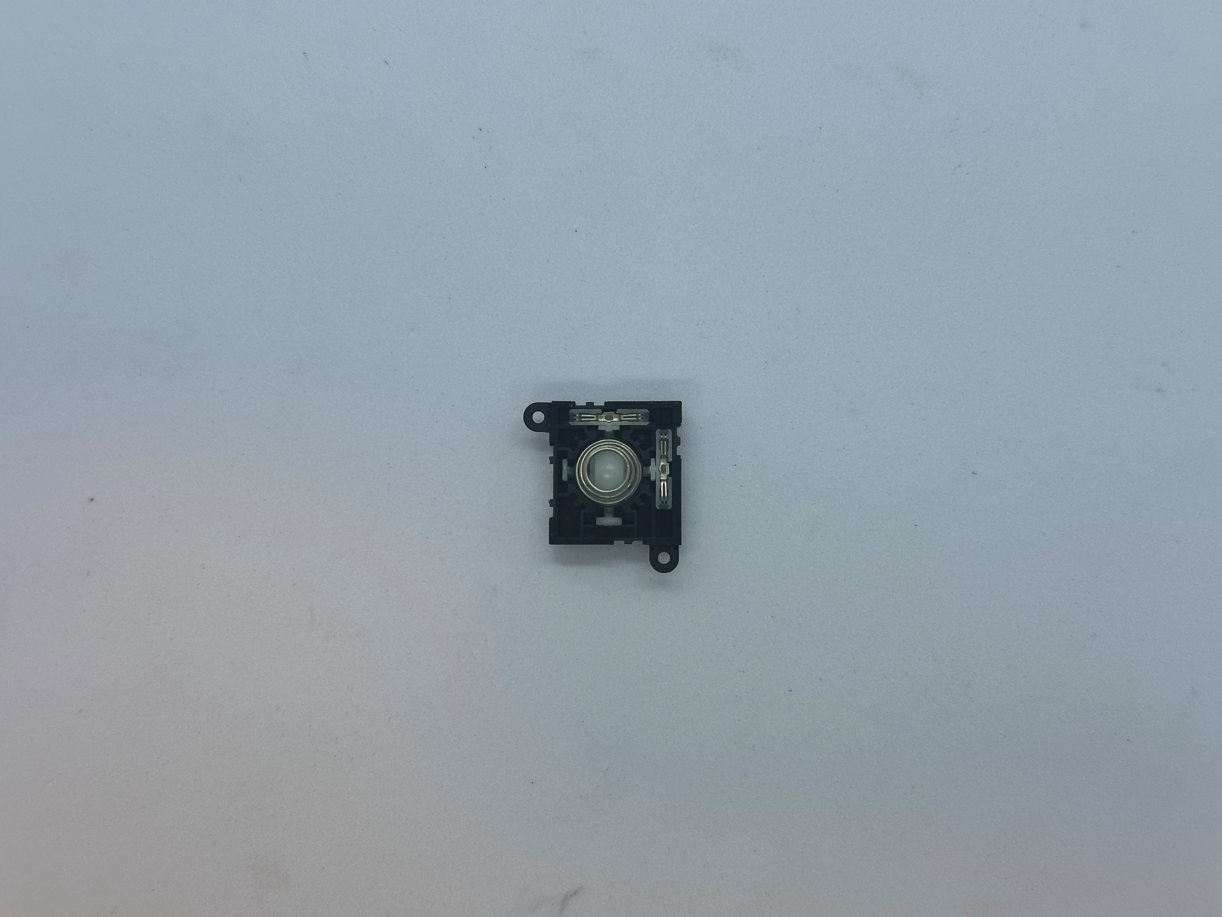
- Retrieve a joystick from Bag G2. Grip the joystick head with pliers and carefully rotate it
90°counterclockwise. Keep the pliers as flat as possible. The stick should detach from the mechanism. Dispose of the joystick head. Sometimes, the stick may break during removal, leaving a bit of plastic inside the base of the mechanism. This is not a major issue, the plastic can be removed later, but it can be quite difficult.
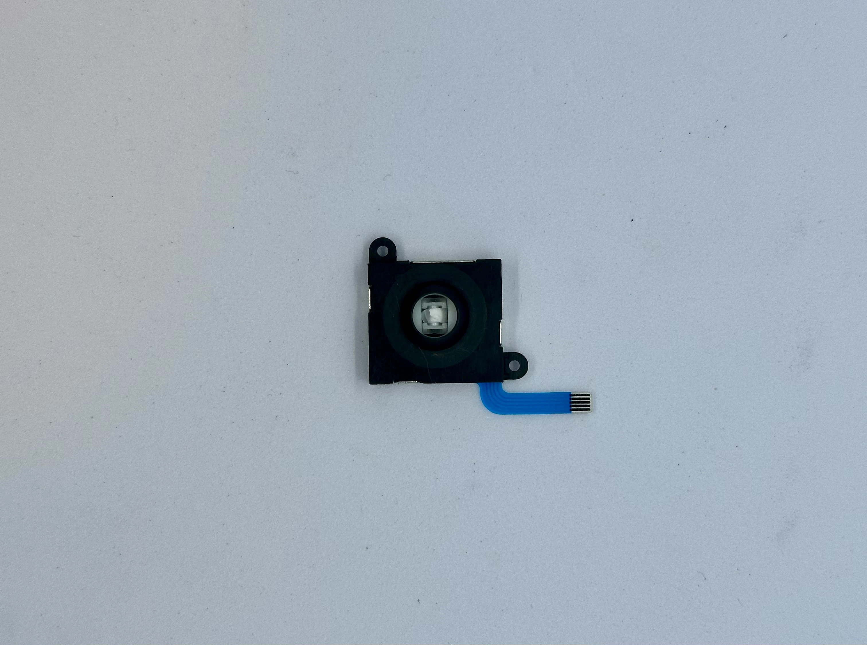
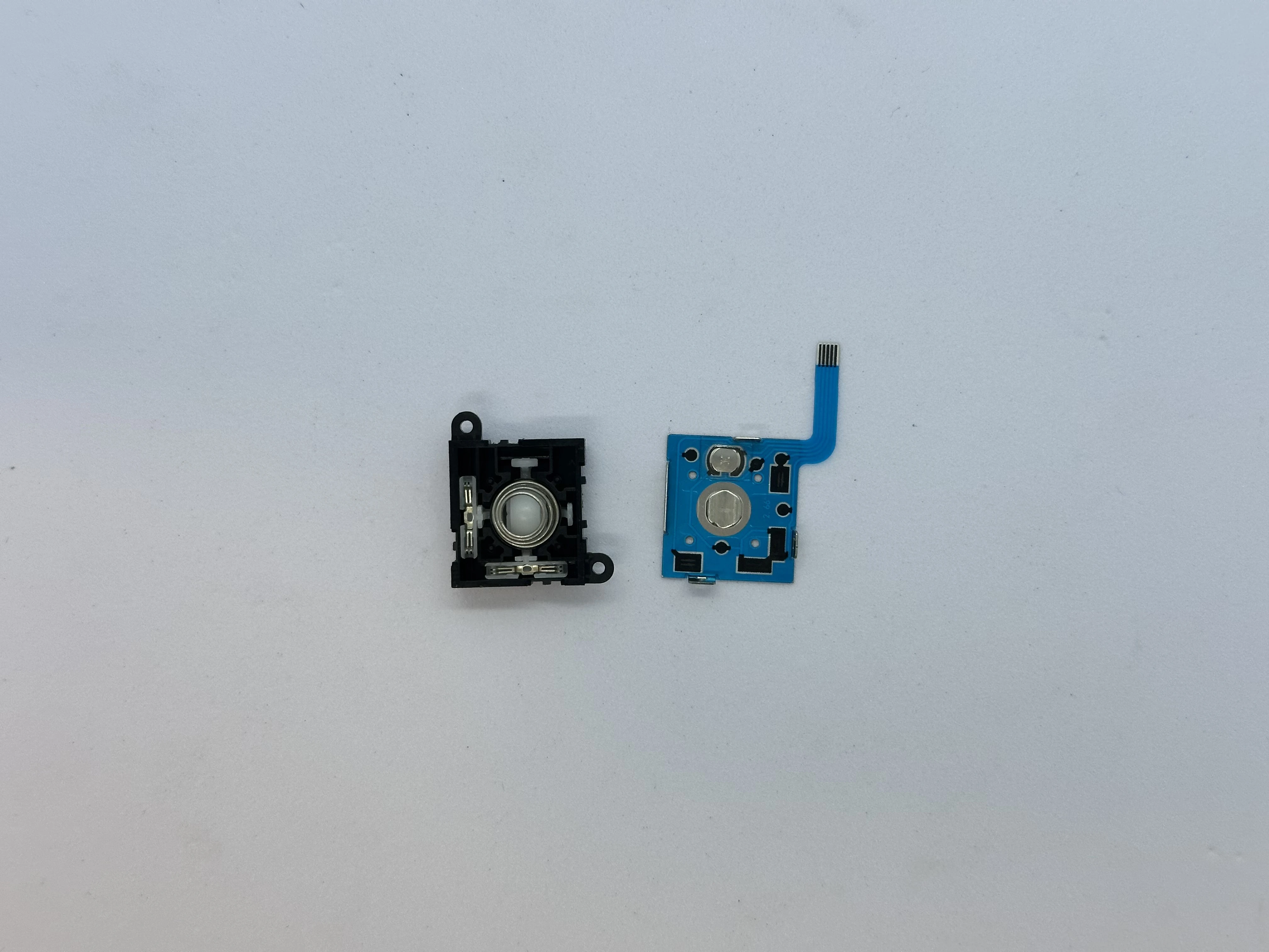
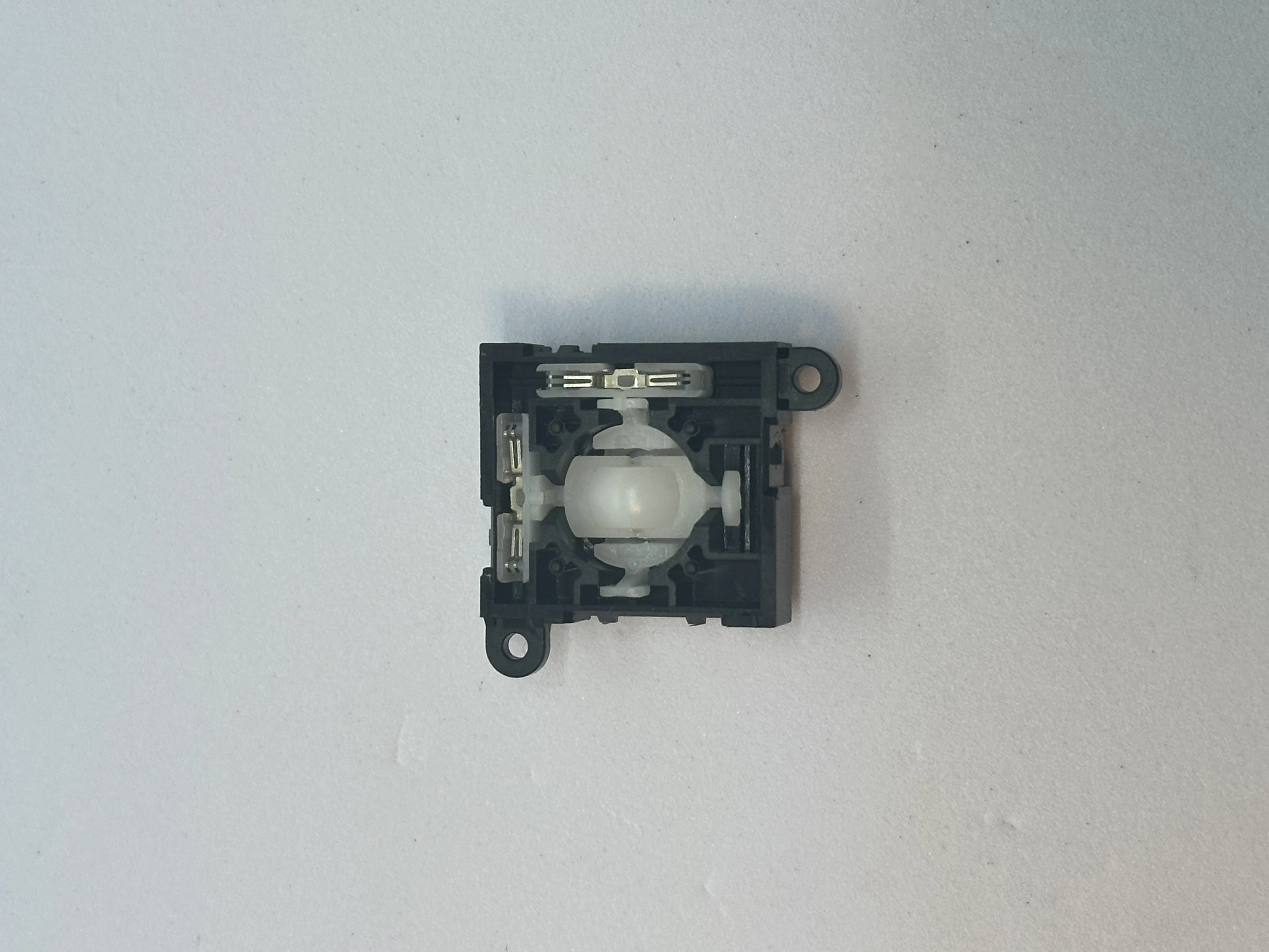
- Remove the back metal cover from the joystick assembly. There are four clips, use an X-ACTO blade to slightly bend the three small clips. The metal plate will then detach. Be careful not to lose any small parts.
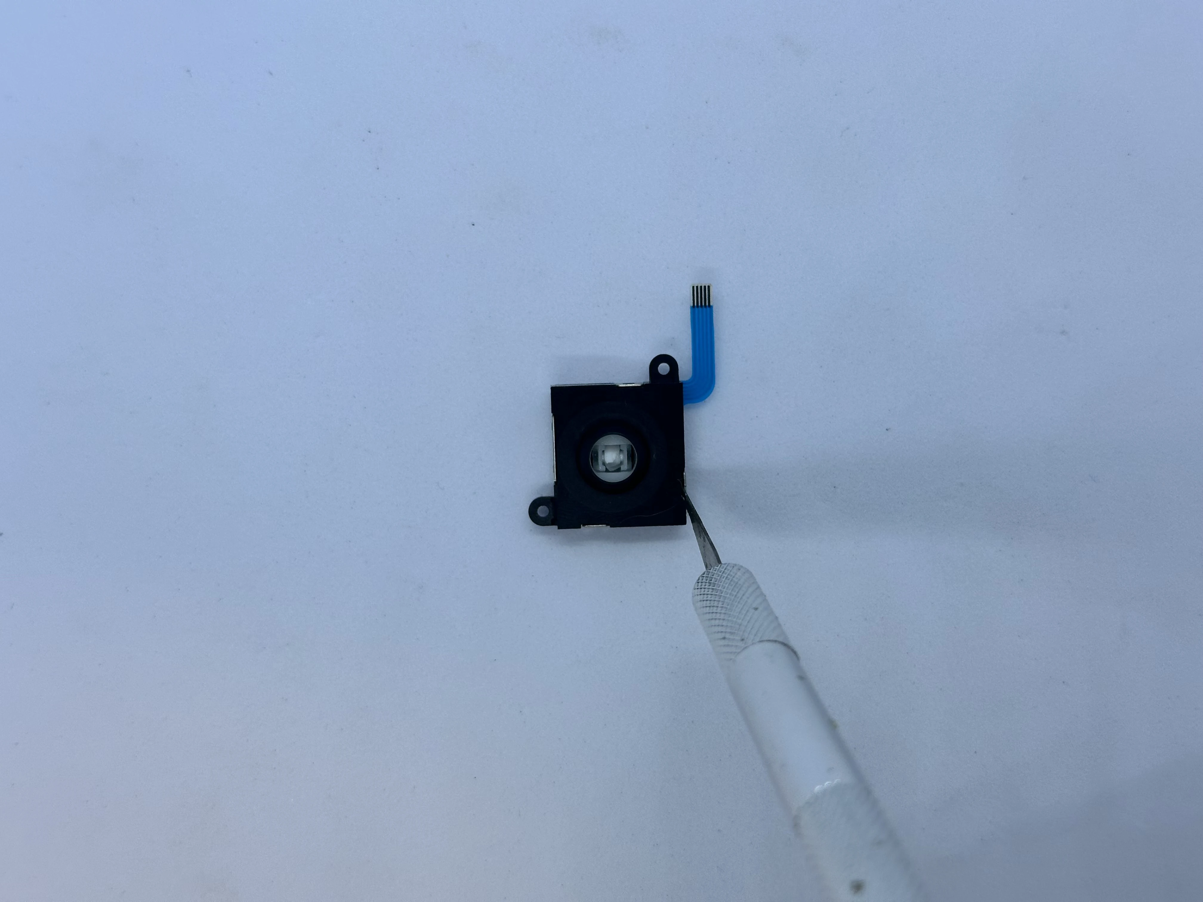
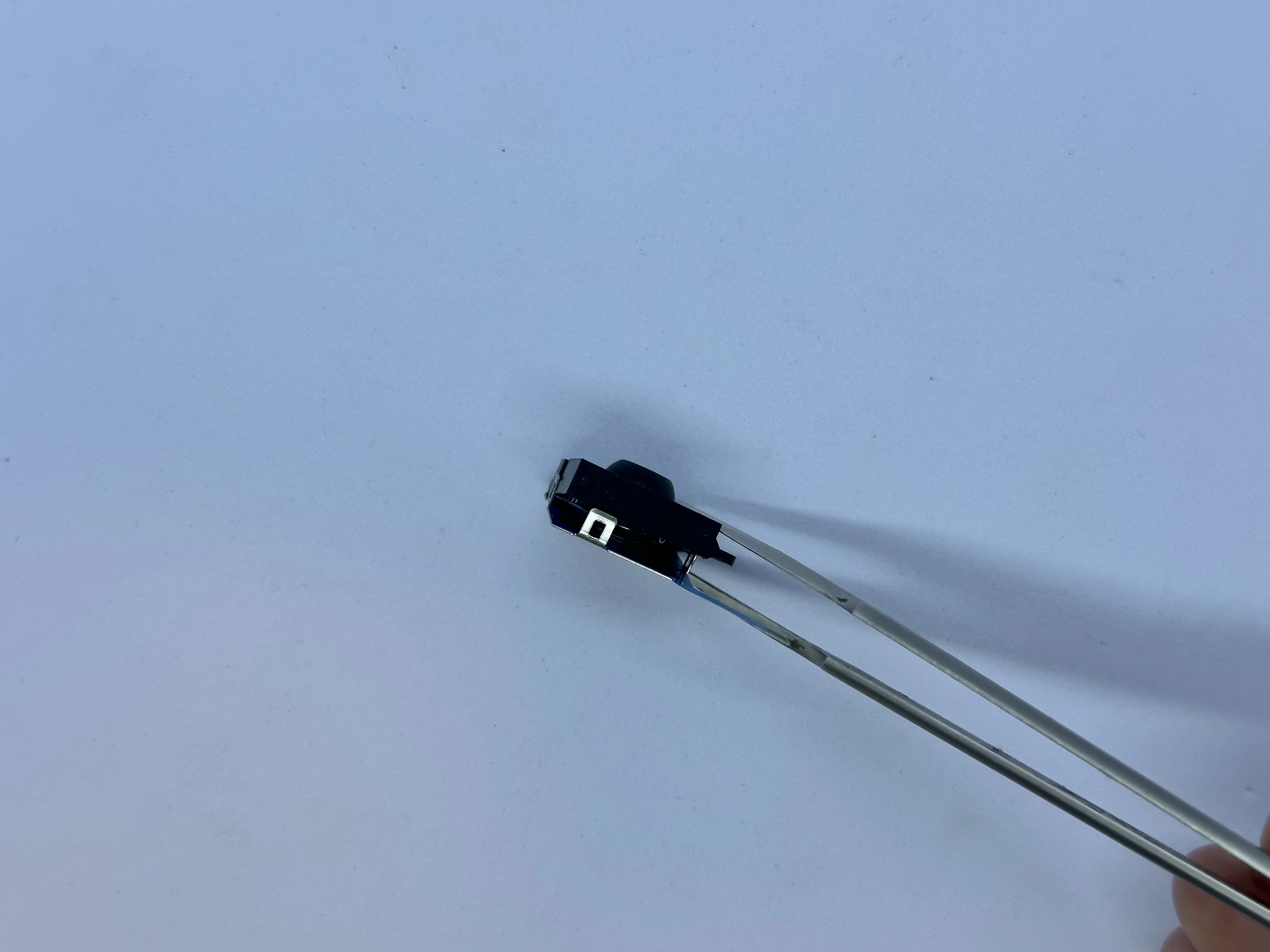
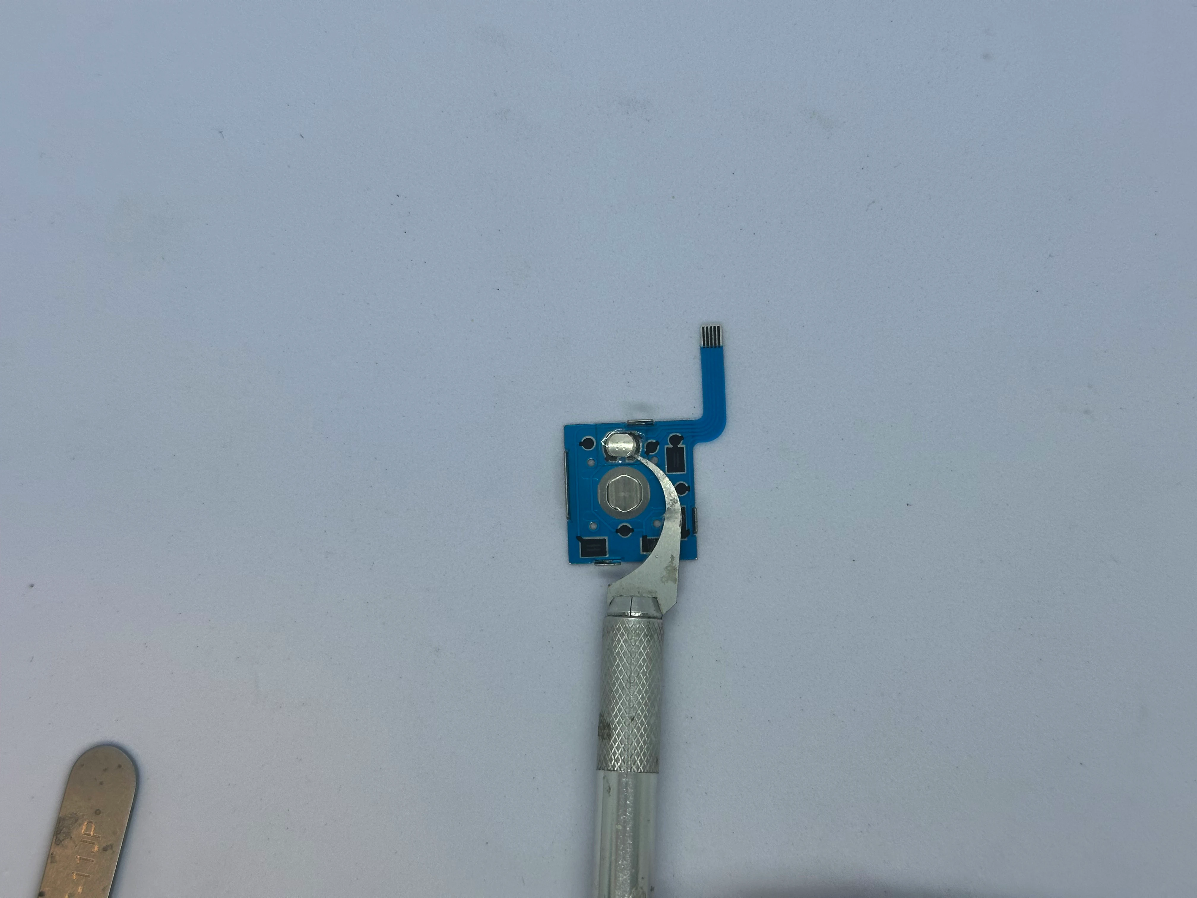
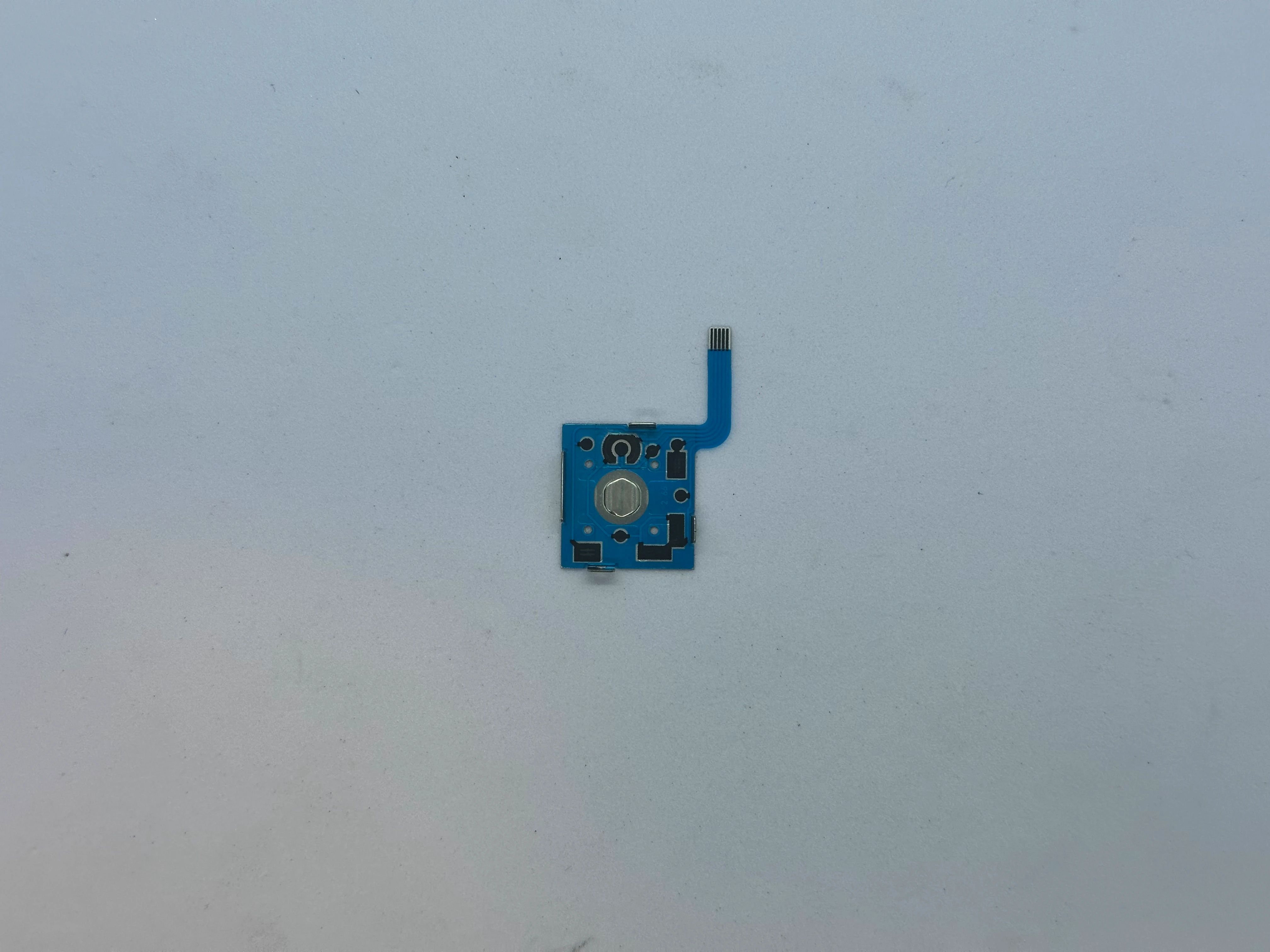
- On the FPC, carefully peel off the button using an X-ACTO blade. The button consists of an adhesive sticker with a small metal dome.
- If part of the joystick head broke inside the mechanism, remove the small white mechanical parts from the top section to clear the area. Then, use two pliers to remove the remaining part of the plastic head.
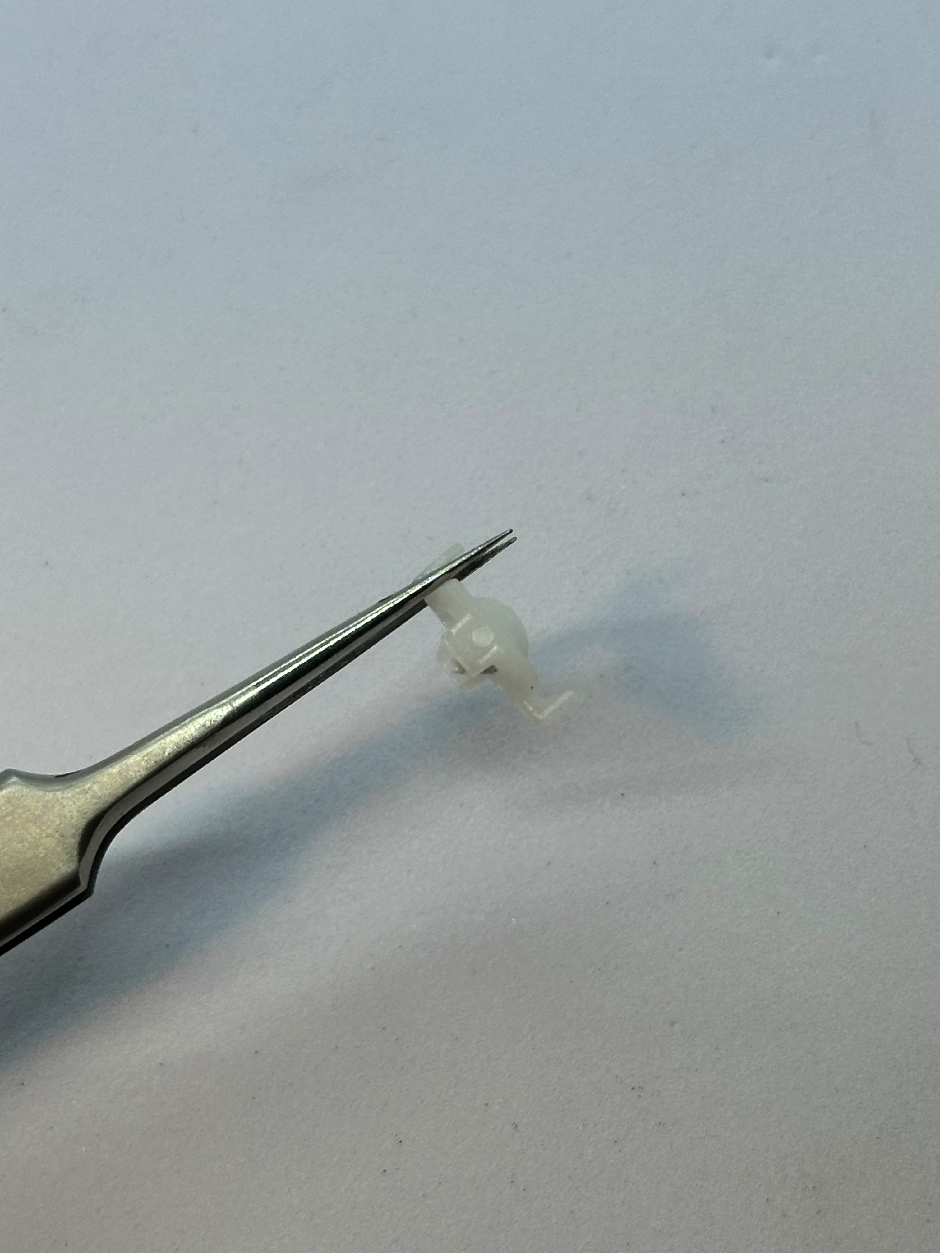
- Reassemble the joystick in the same way as before. Then install the 3D printed trigger by pressing the trigger down firmly from the top until it clicks into place.
Test the trigger to ensure it moves smoothly. If the movement is rough, remove the 3D printed trigger. Then, use a lighter for a moment by the bottom of the trigger. Insert it and repeat until the mechanism feels nice.
Repeat the process for the second trigger.
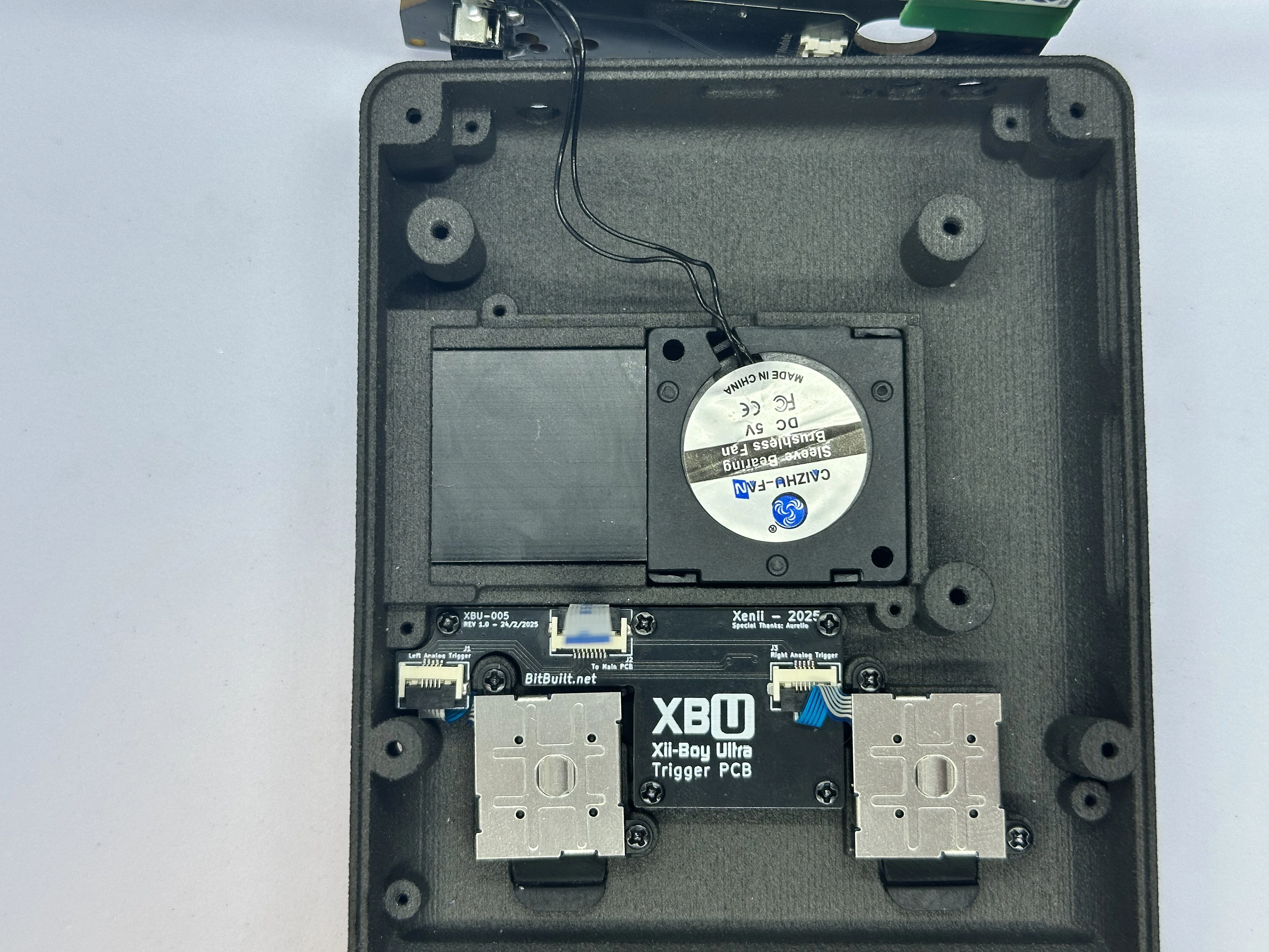
Lower Layer
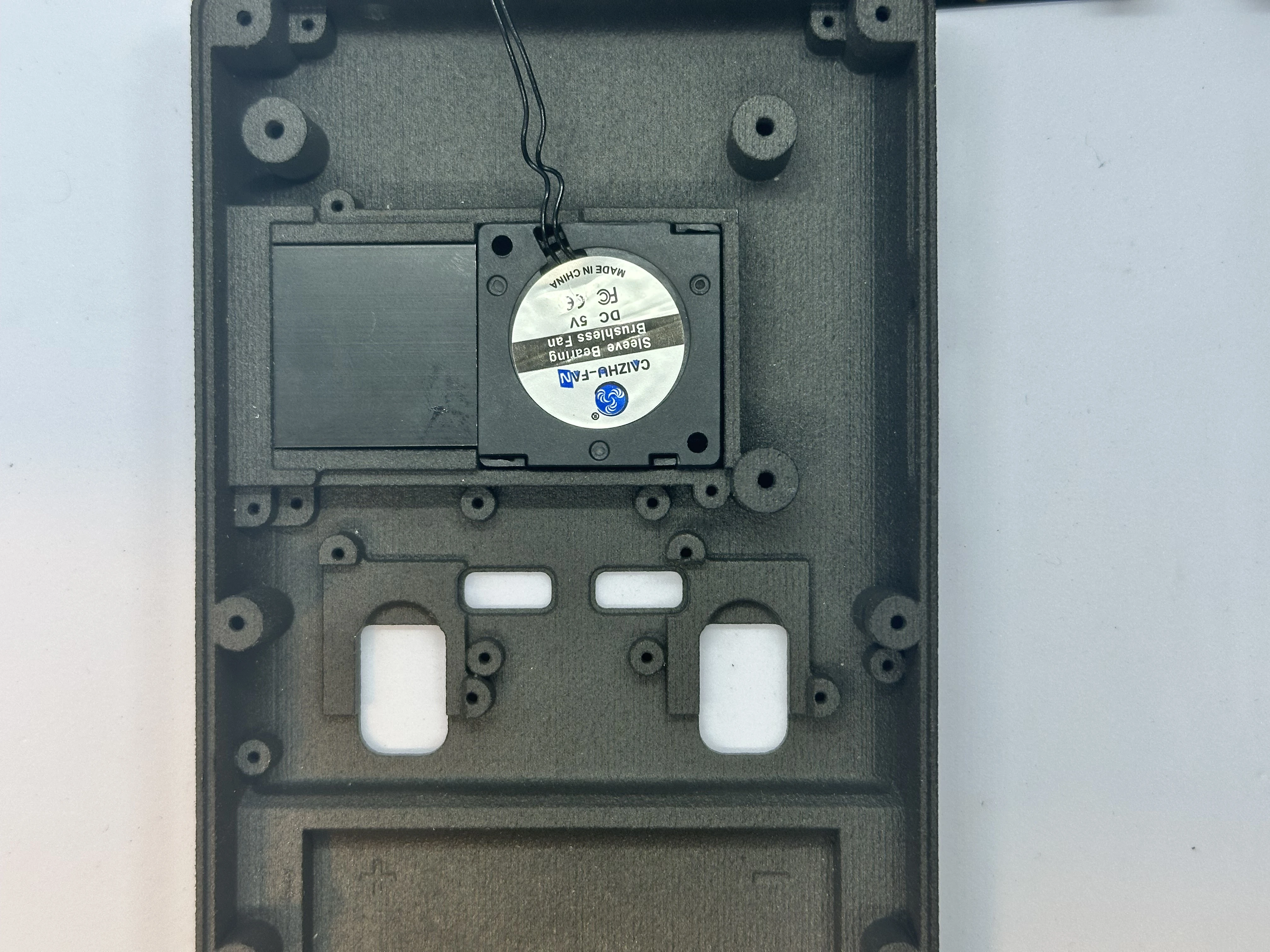
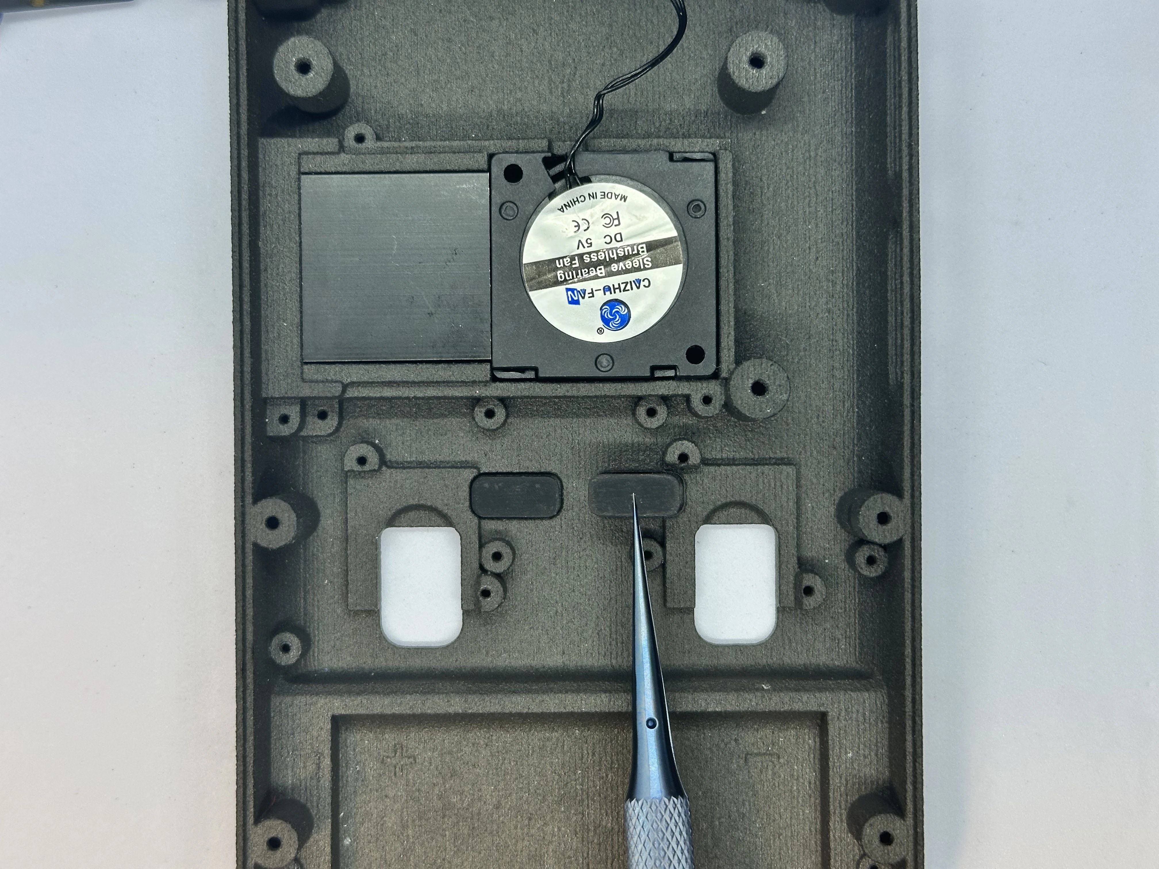
- Install the heatsink and fan. The heatsink should be placed in the orientation that aligns the arches with the arches on the shell. The fan must be installed so that the cable faces the USB-C port and the top of the shell. There is a small notch in the shell that allows the cables to pass through.
- Place the RZ and LZ bumper buttons.
Important
GUIDE NEEDS UPDATED - PLACE WIFI ANTENNAS (STEP 8) BEFORE FASTENING THE TRIGGER PCB BOARD
- Connect the two modified Joy-Con Joystick Triggers to the Trigger PCB ZIF connectors.
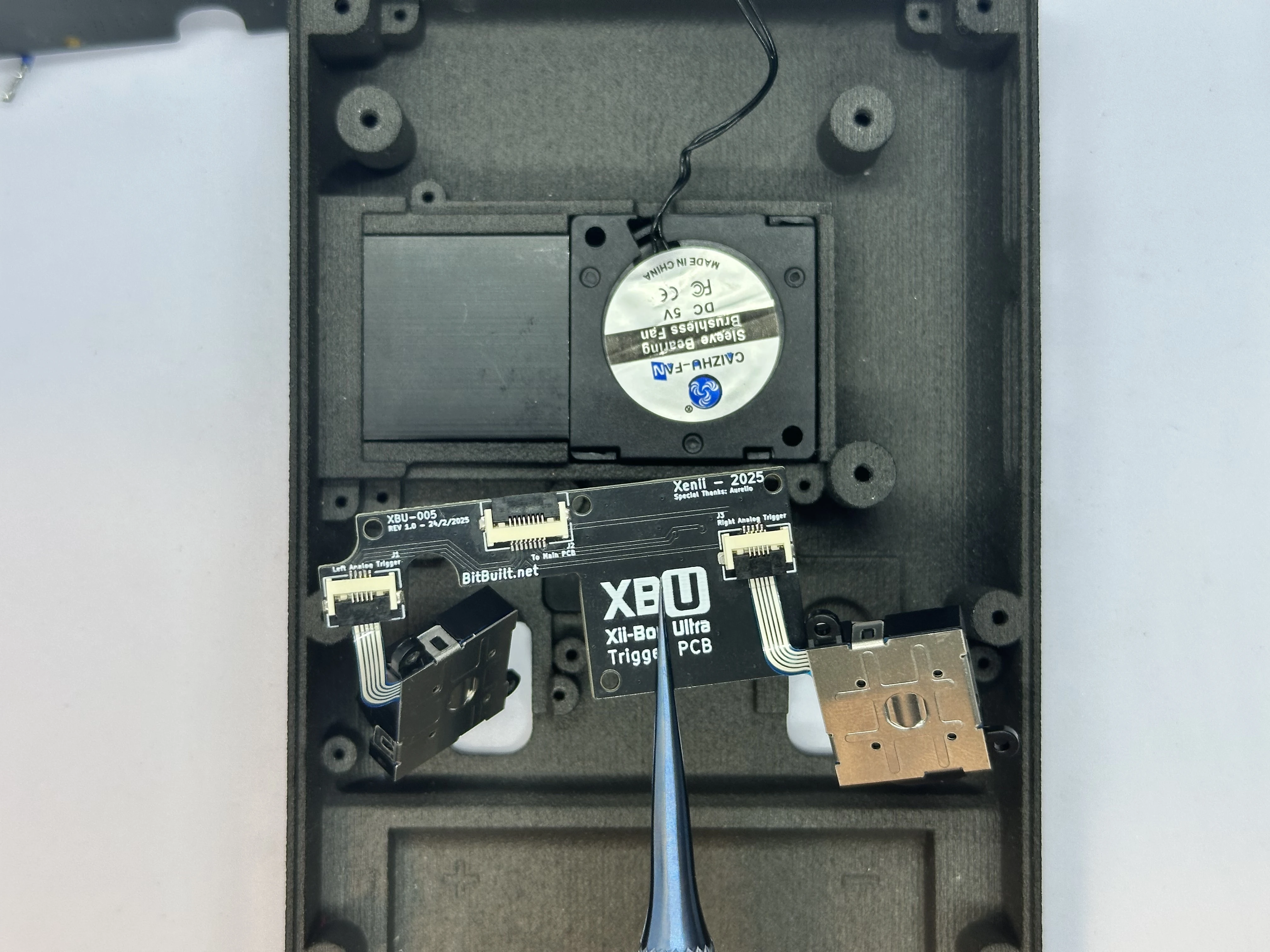
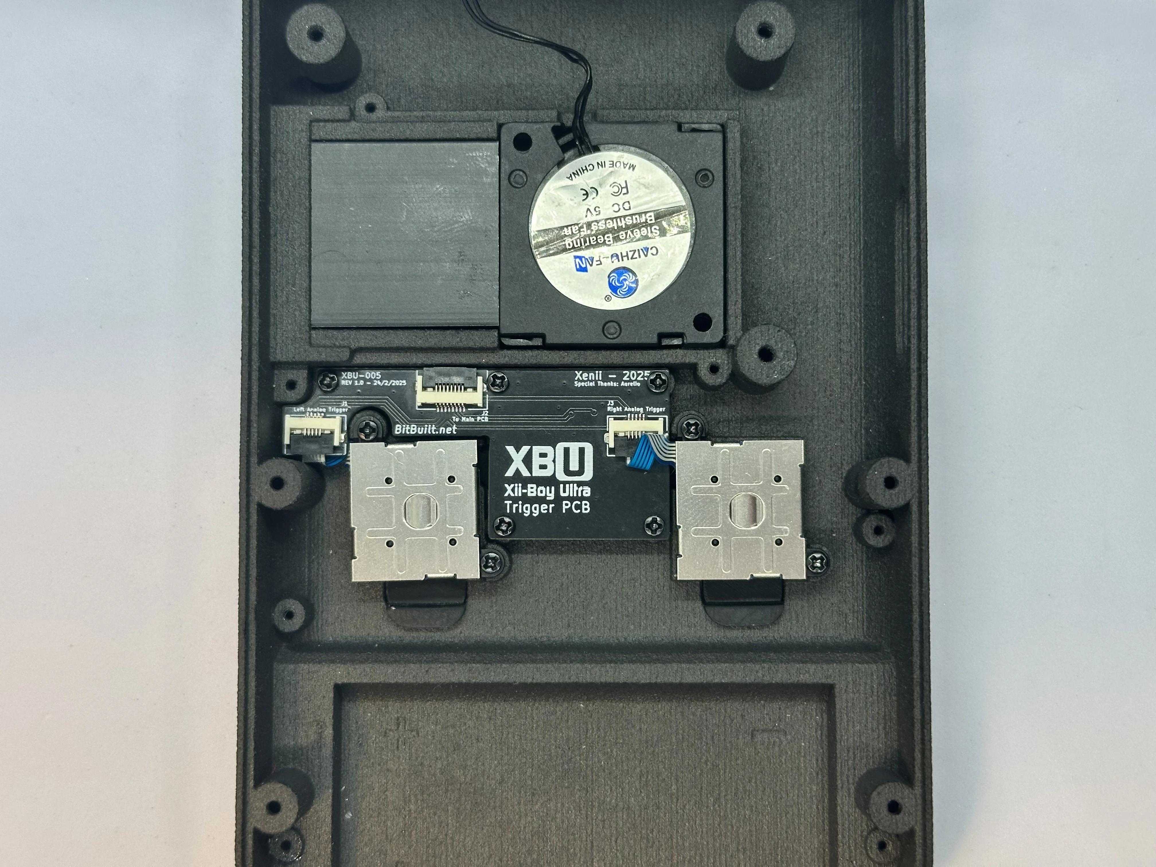
- Align the Trigger PCB and triggers with their respective screw posts. Fasten the Trigger PCB with five
4mmPhillips screws, and fasten the triggers with two4mmPhillips screws each.
INFO
The ribbon cables on the triggers will need to be bent in order to fit properly.
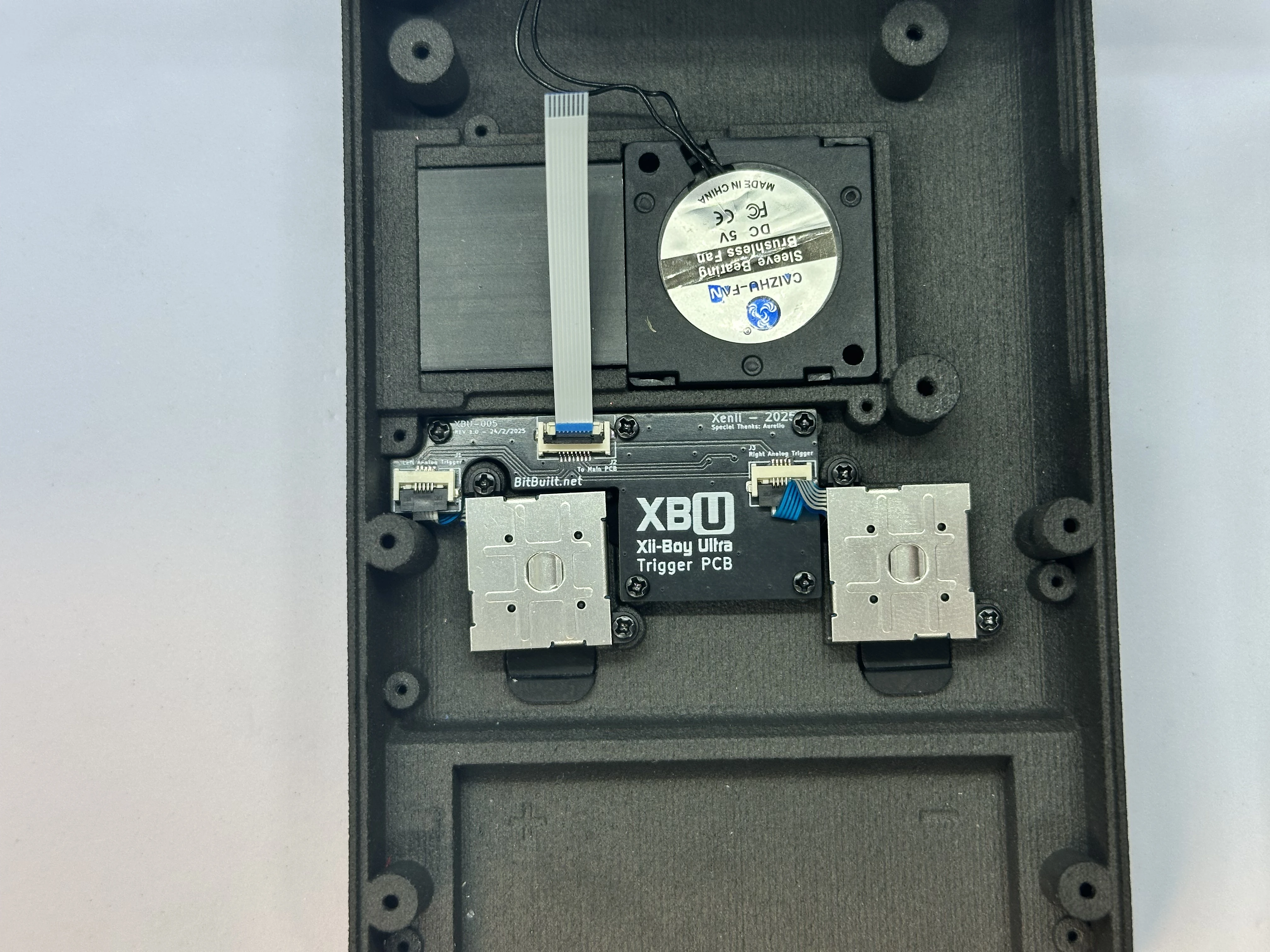
- Unlock the 8 Pin ZIF Connector on the Trigger PCB labeled “To Main PCB”. Insert the 8 Pin FFC and lock the connector. Bend the cable so that it is facing straight up - 90° from the connector.
- Apply Arctic MX-4 thermal paste to the heat sink in an “X” shape. Apply more than what is pictured, but not so much it overflows.
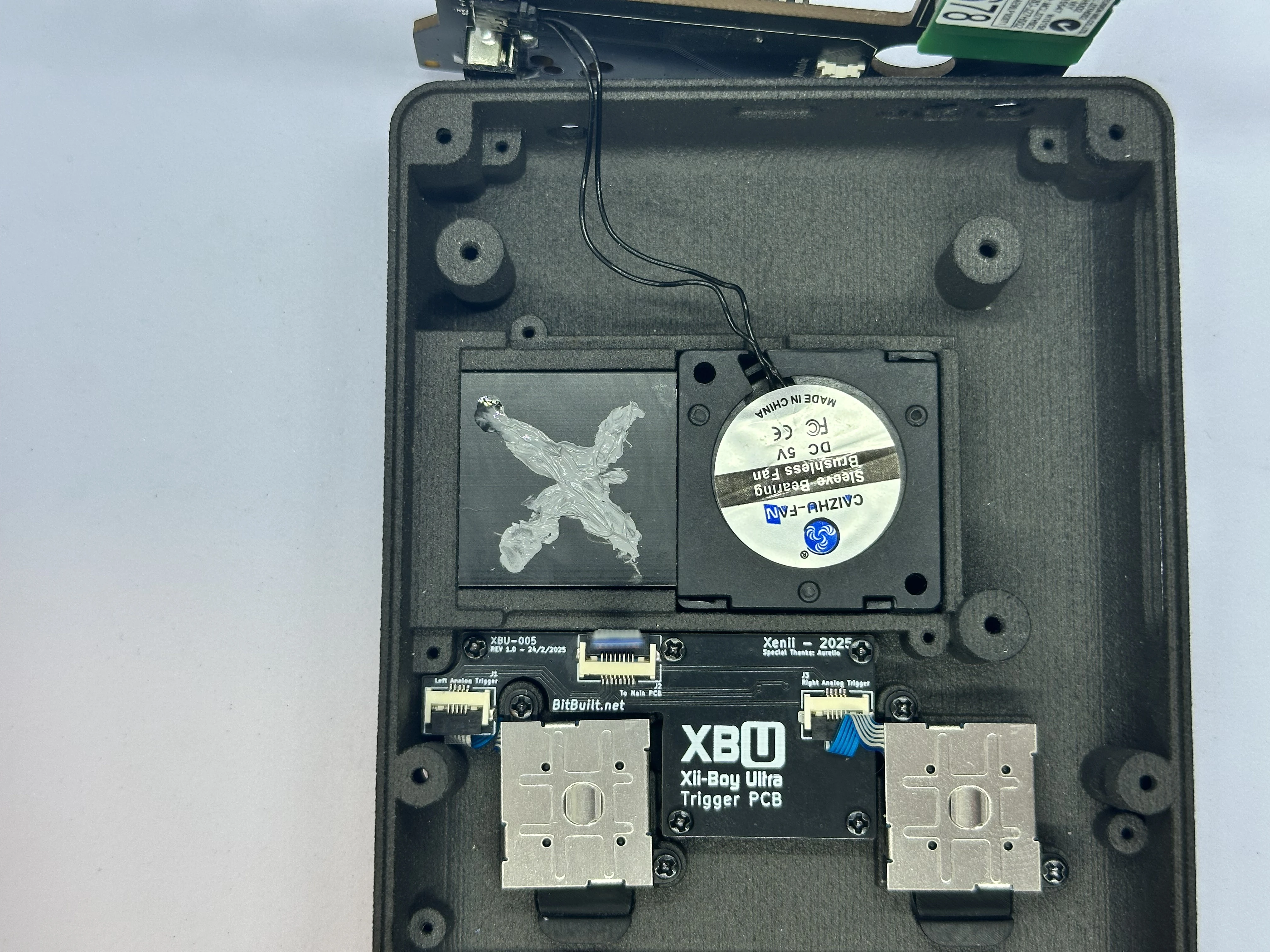
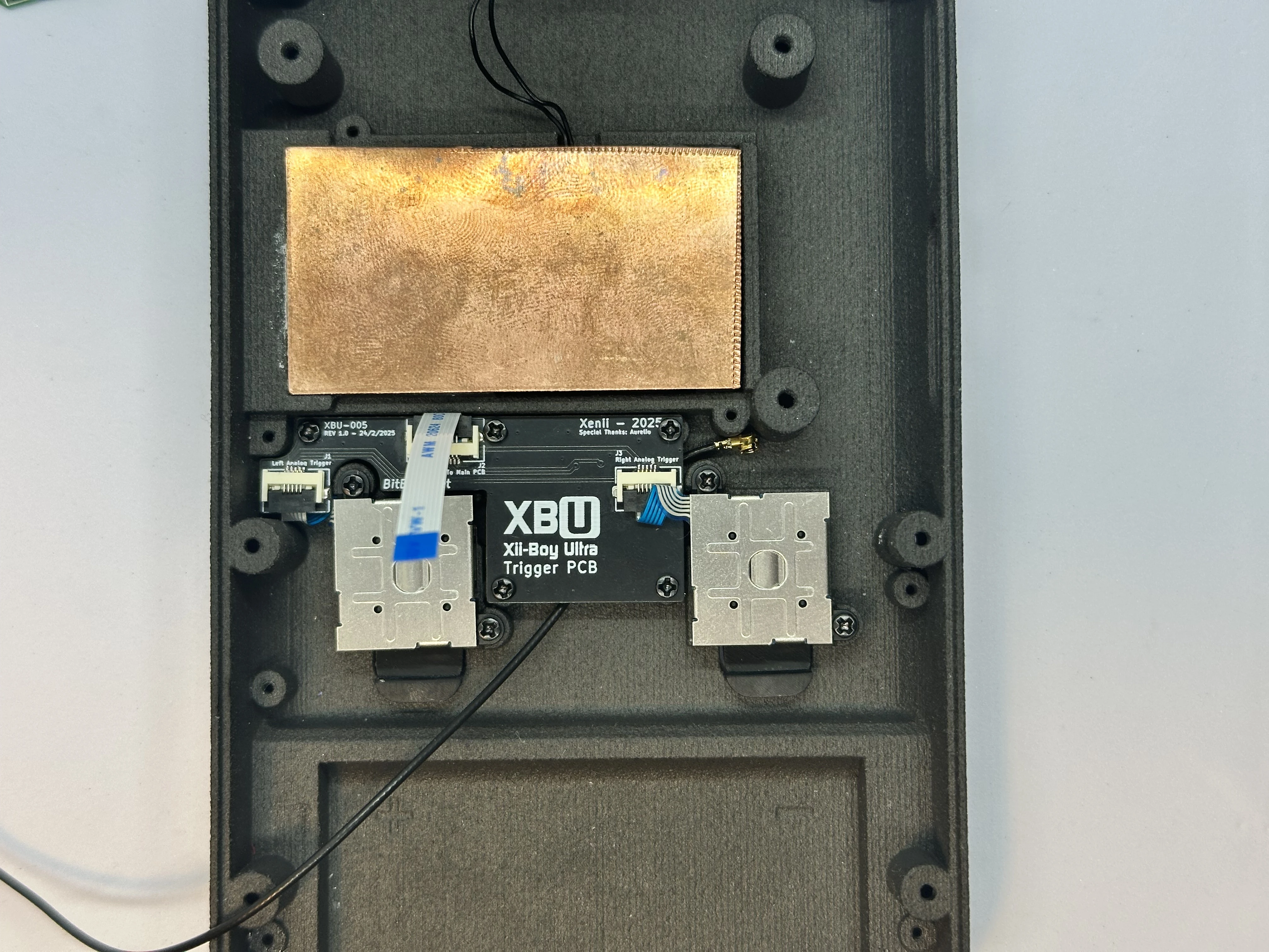
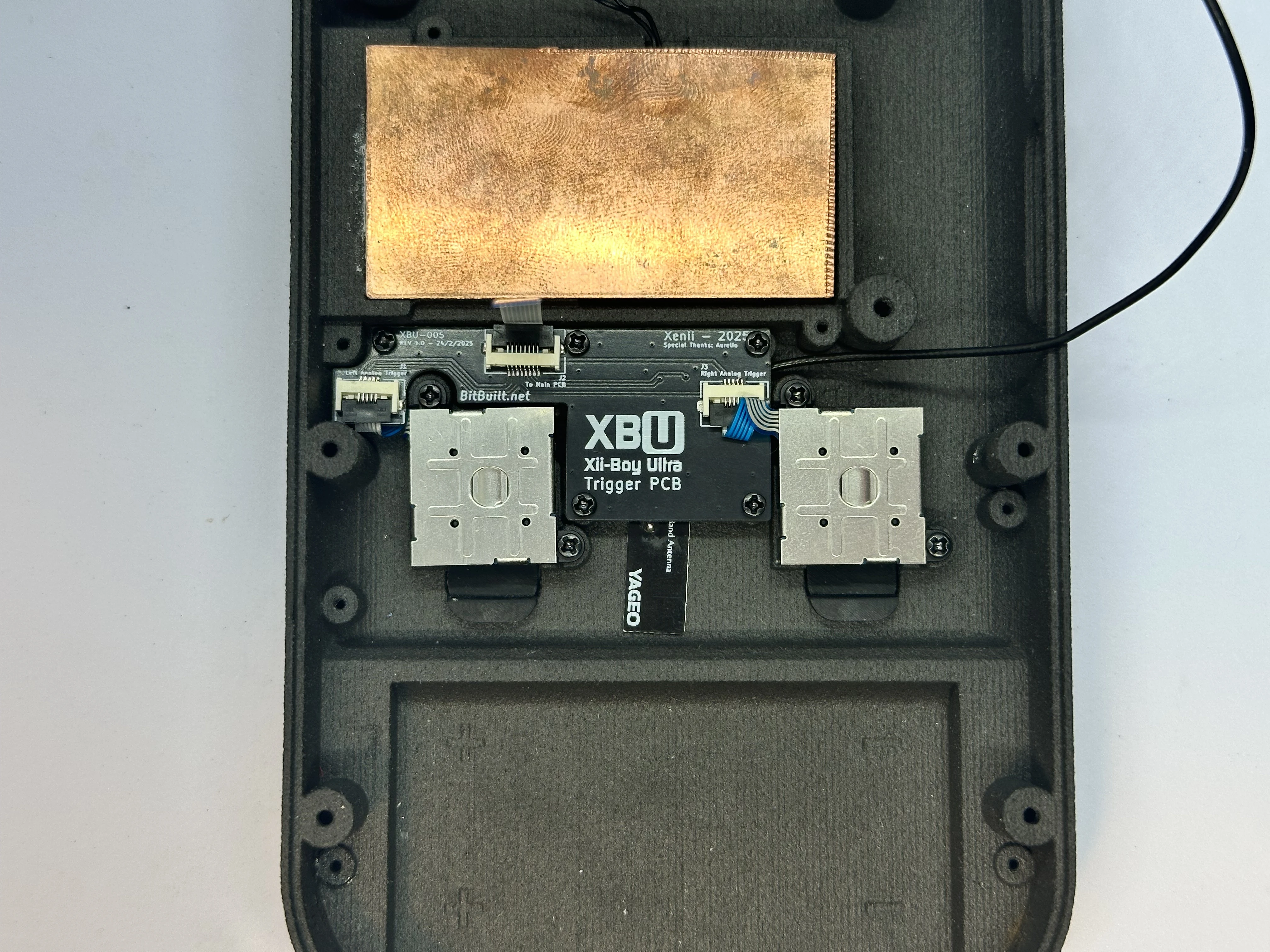
- Firmly place the
30mm x 55mm x 1mmcopper plate over the heat sink and fan.

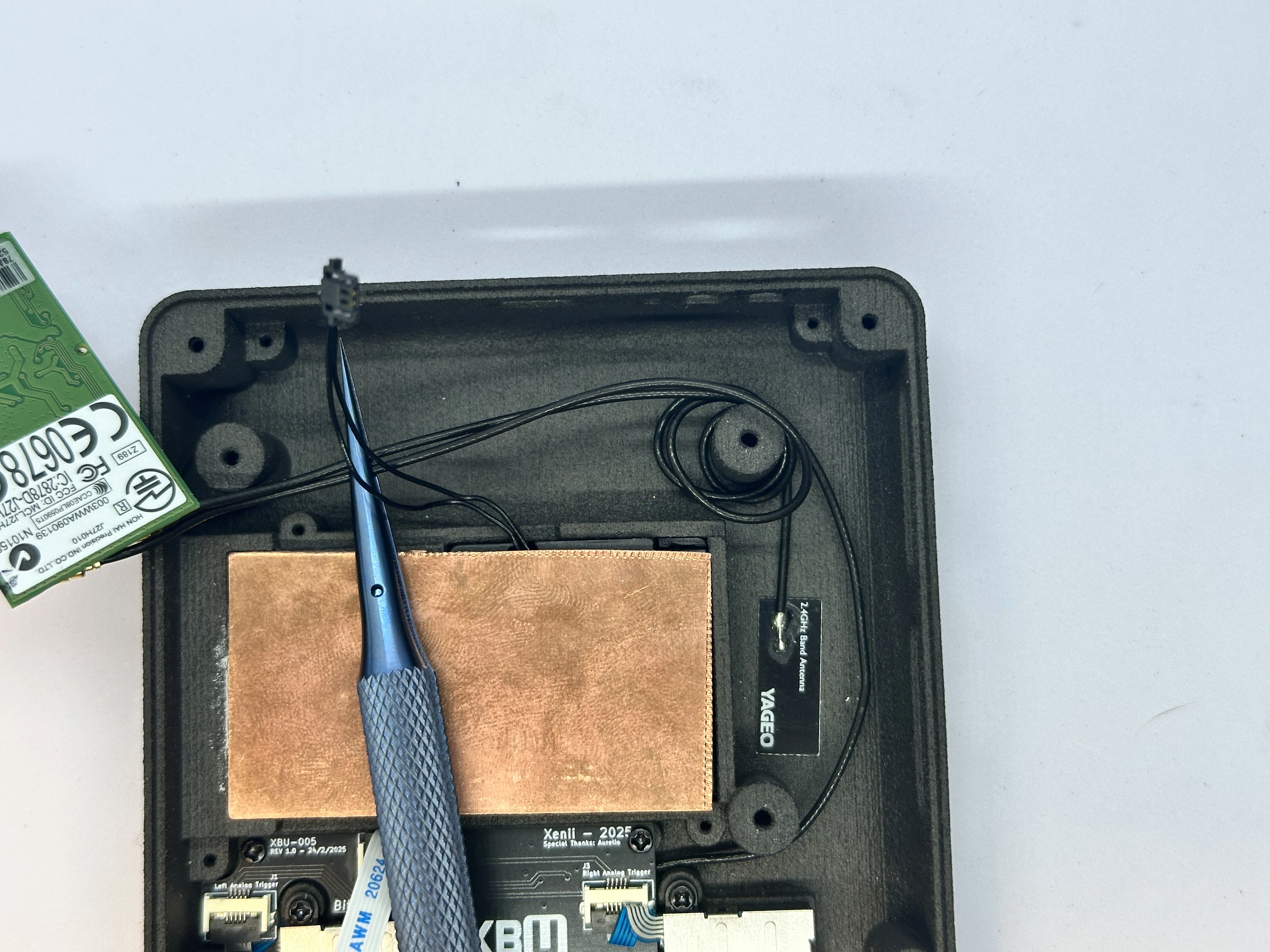
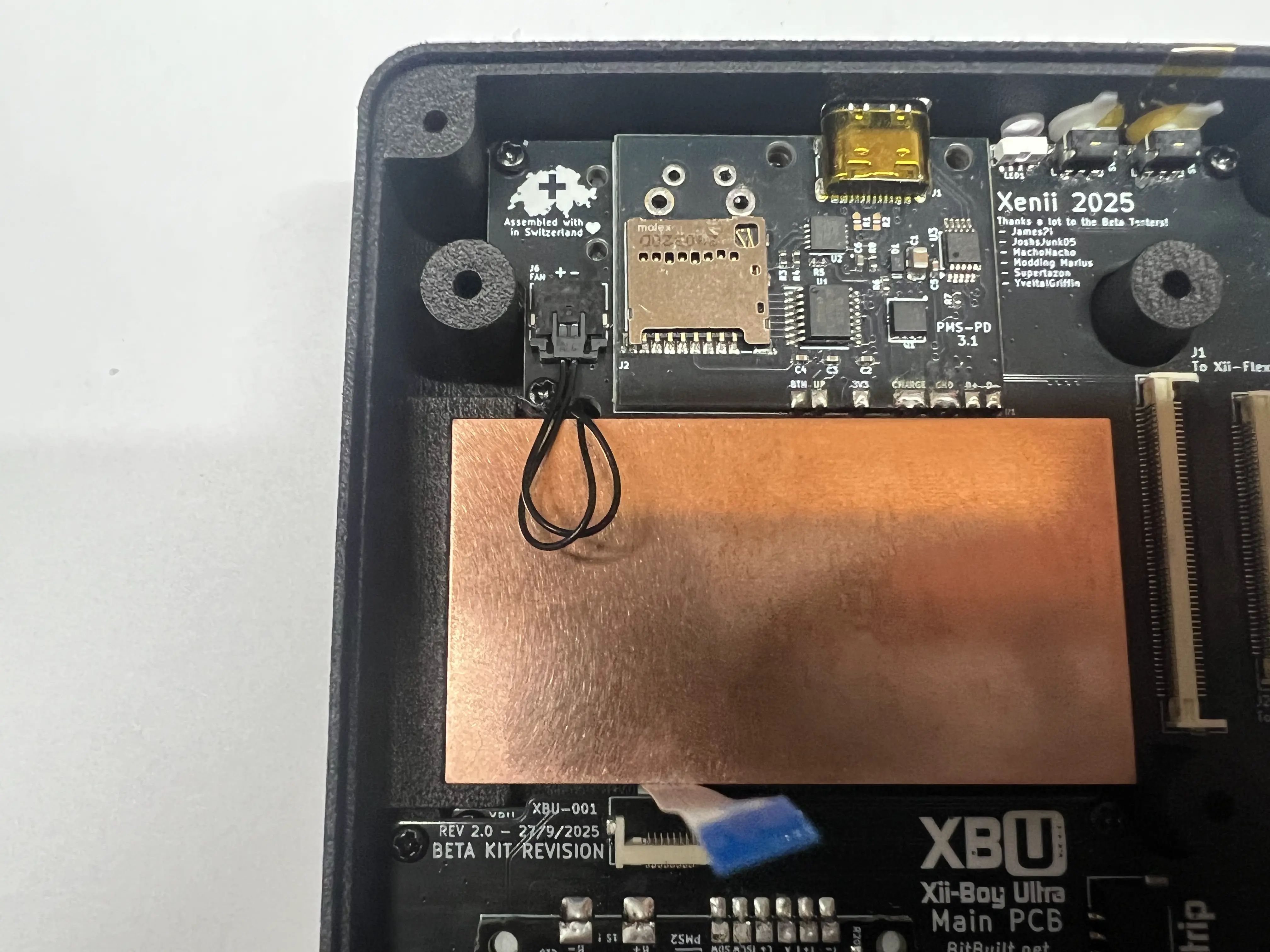
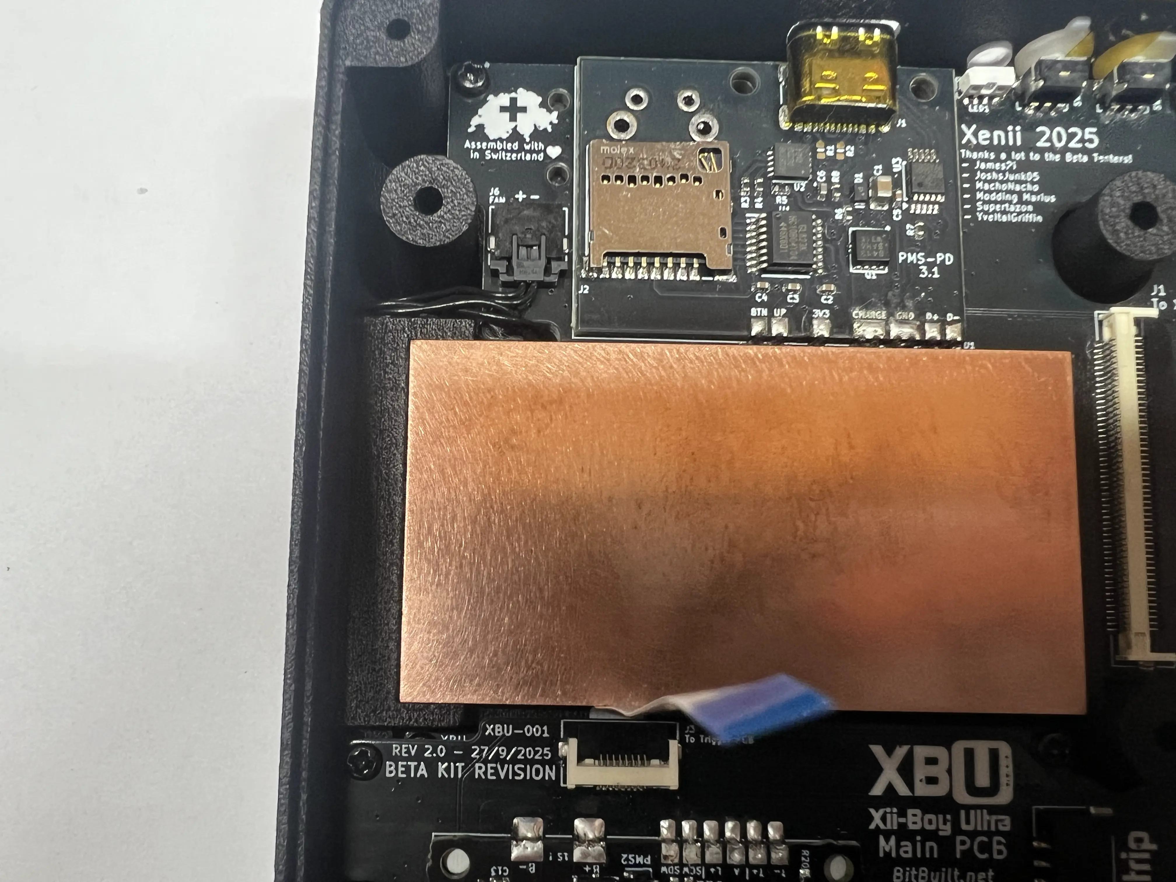
- Remove the white adhesive strips from the two black Wi-Fi antennas and place them as pictured. Wrap each of the wires twice around the upper right screw post.
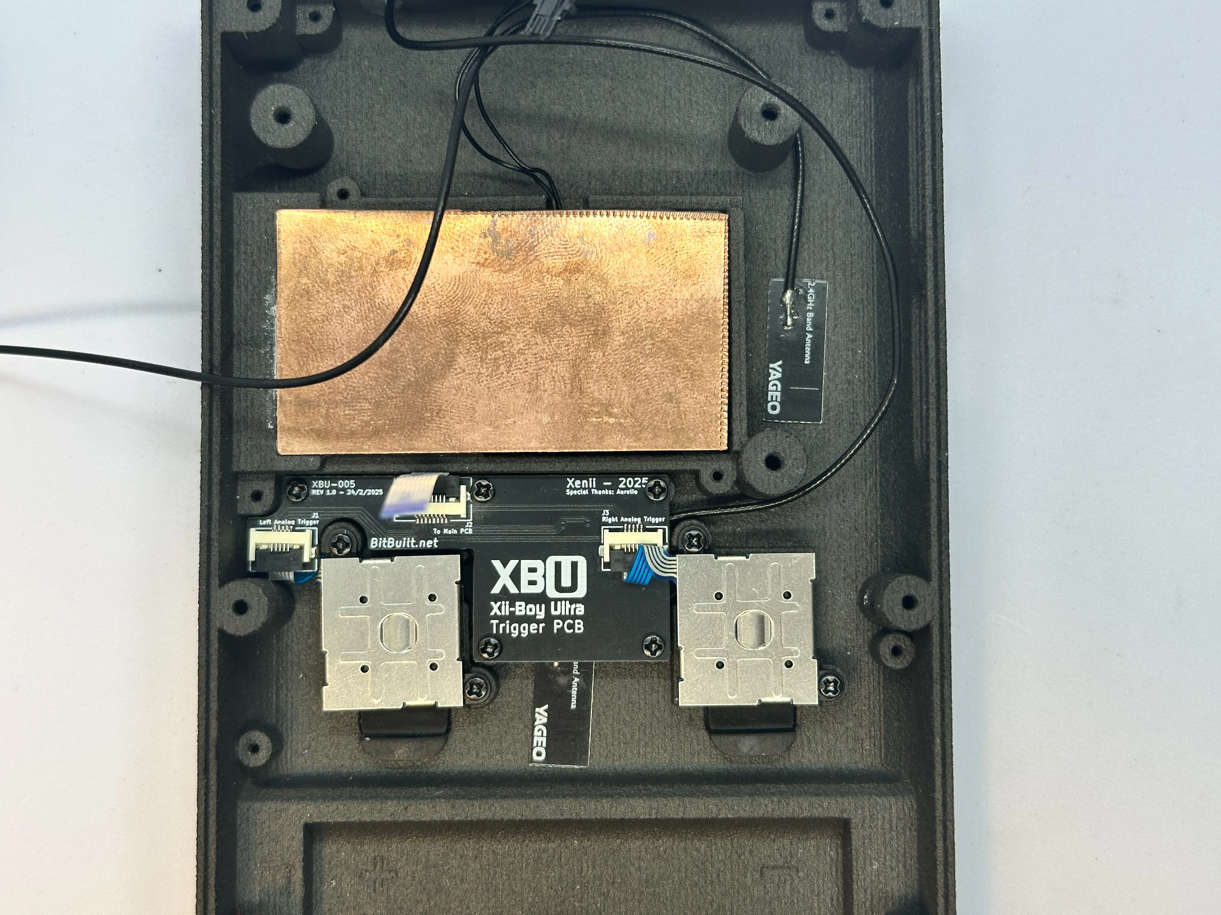
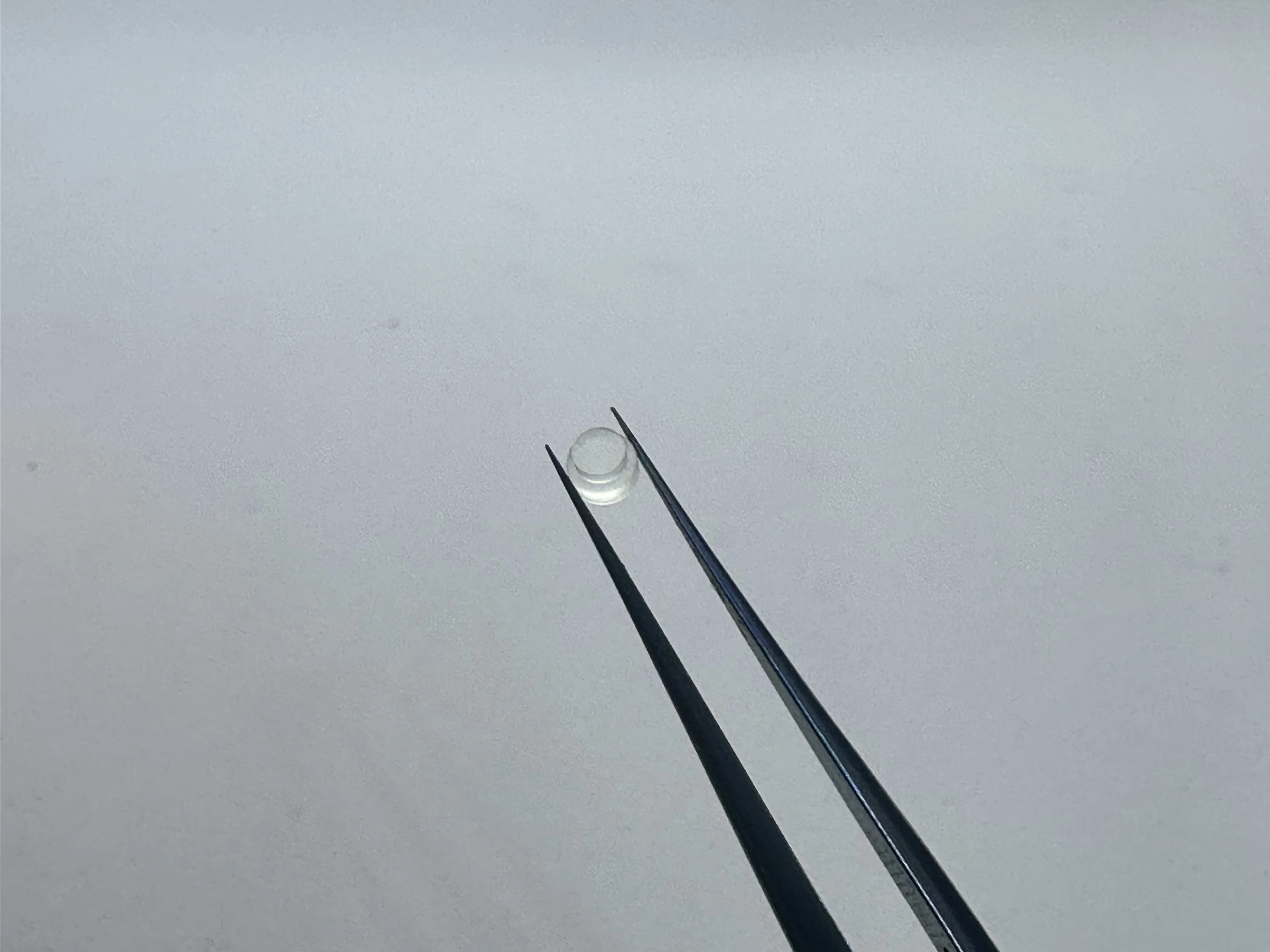
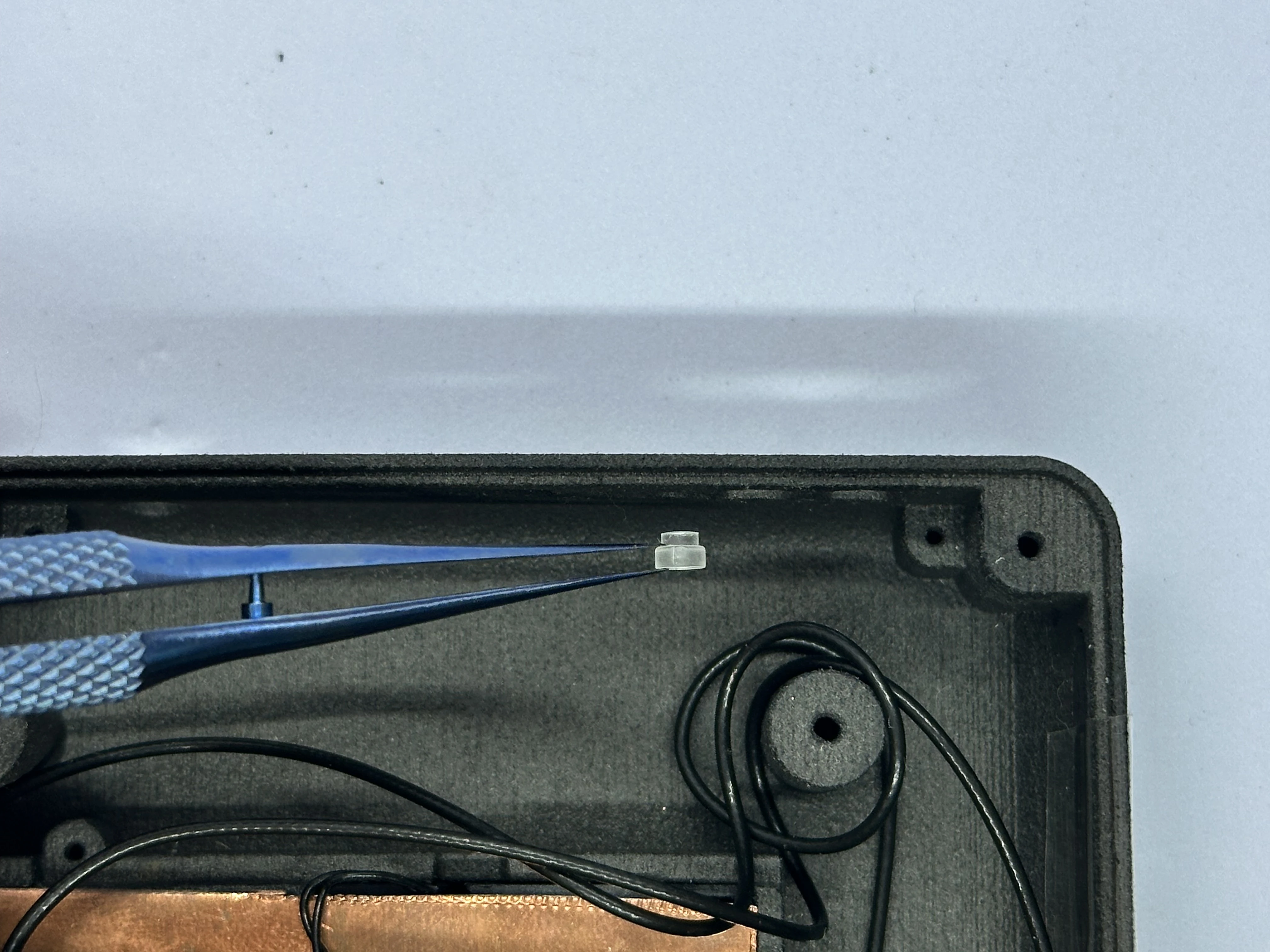
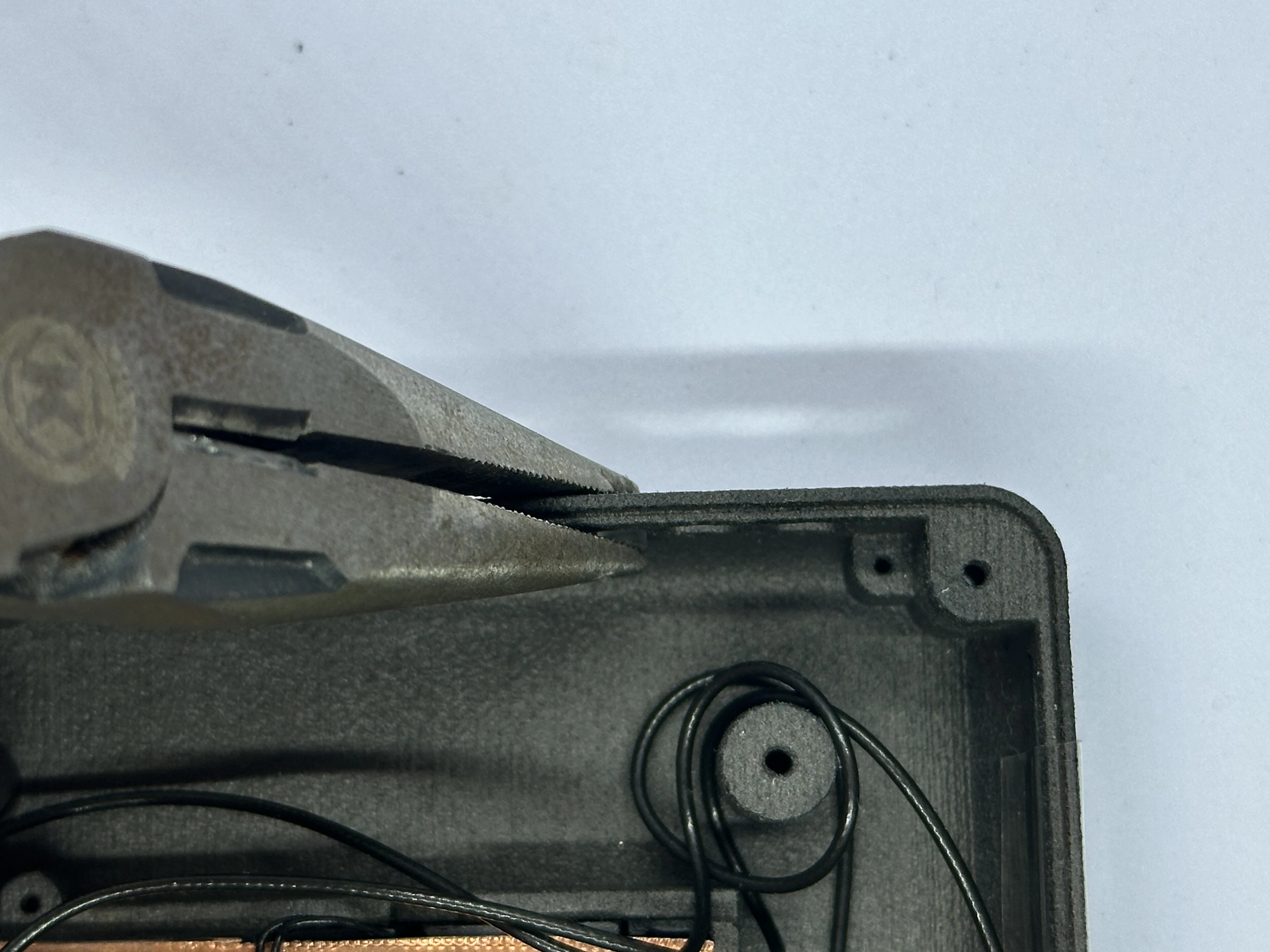
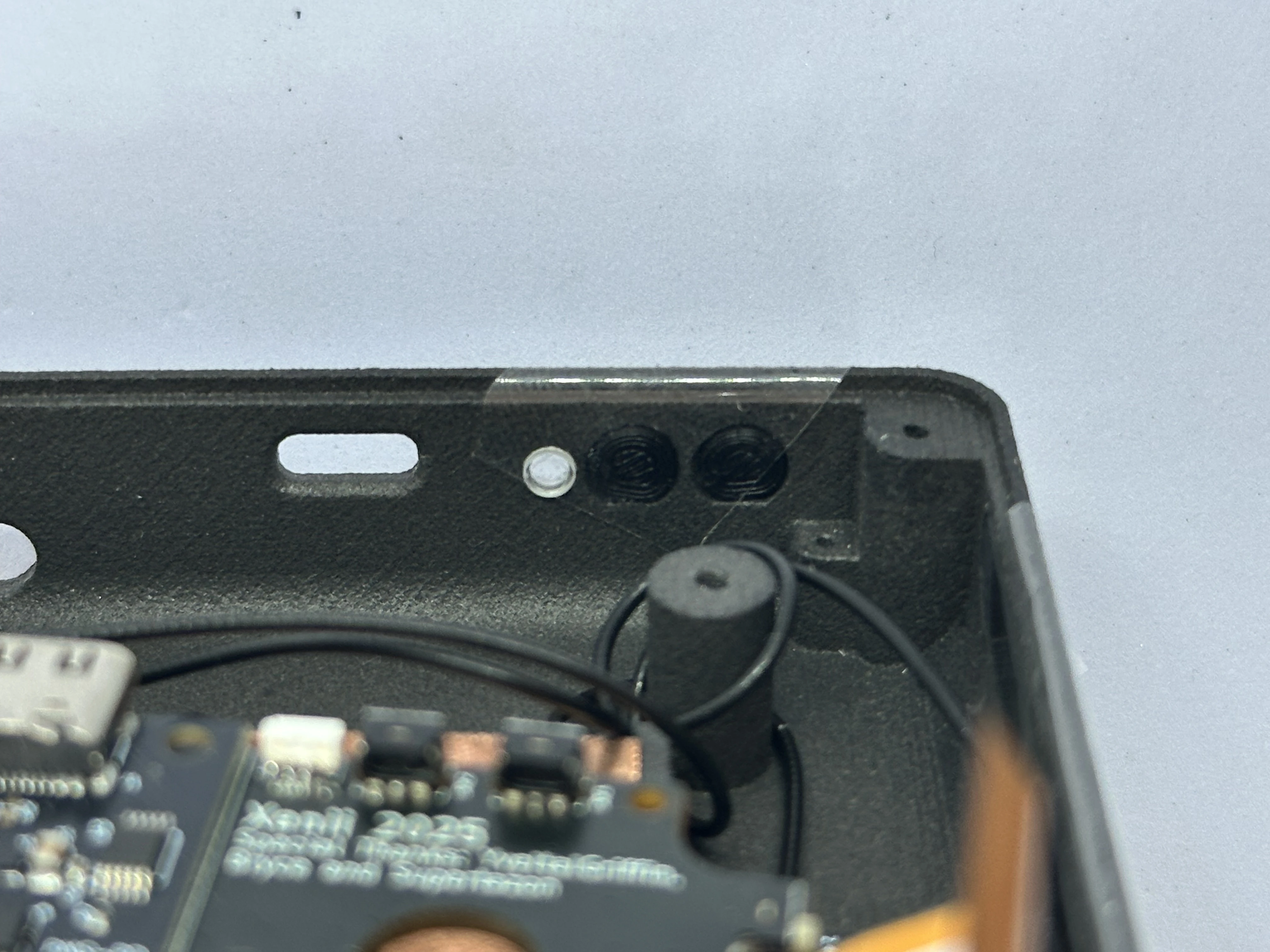
- Take the clear light pipe and a pair of pliers. Position the light pipe at the top of the shell on the left of the power button hole. Carefully use the pliers to push the pipe into place. Do not apply too much force, as this could crack the shell easily.
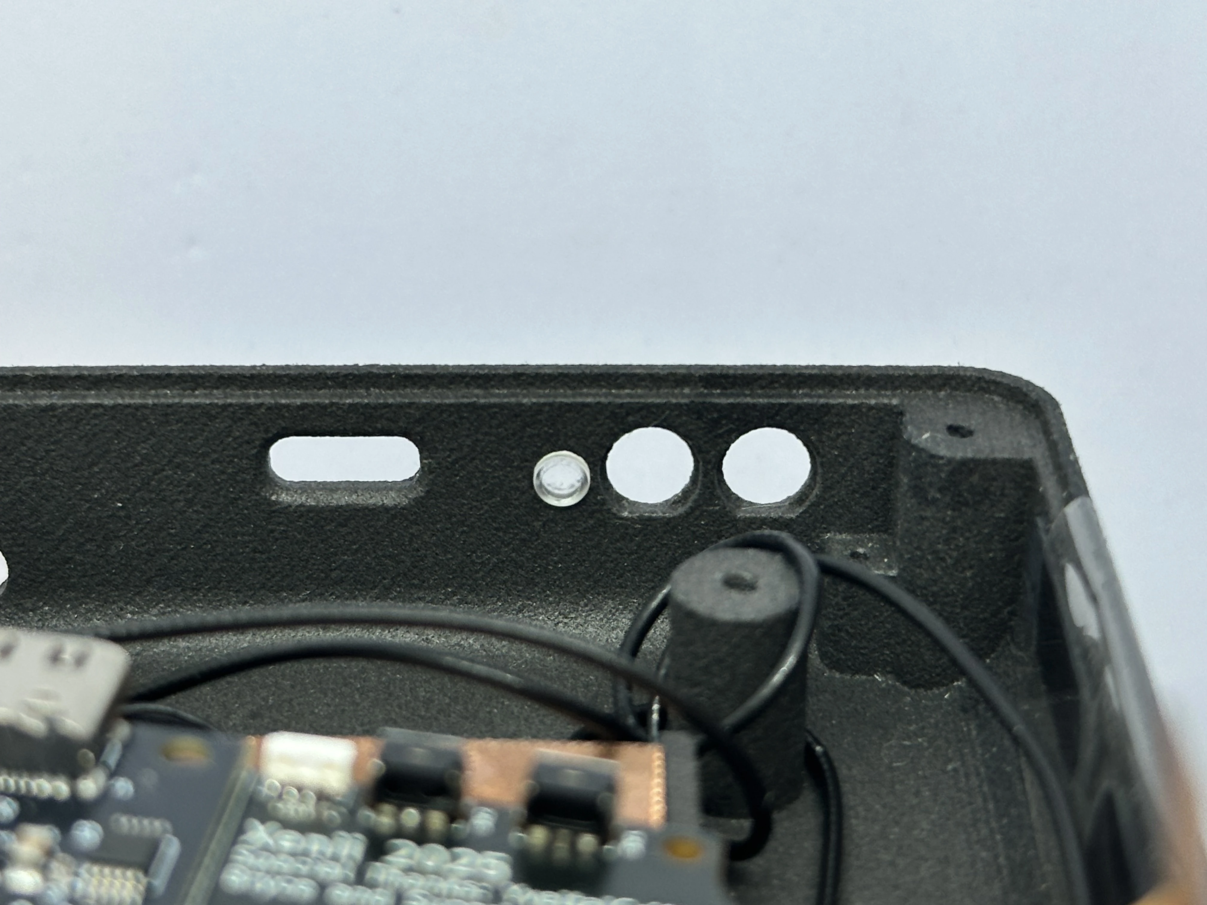
- Place the
Power(closest to the light pipe) andBluetooth Sync(closest to the corner) buttons in their slots. Each button has a notch, so note the orientation. A small piece of tape can be used to keep them in place.
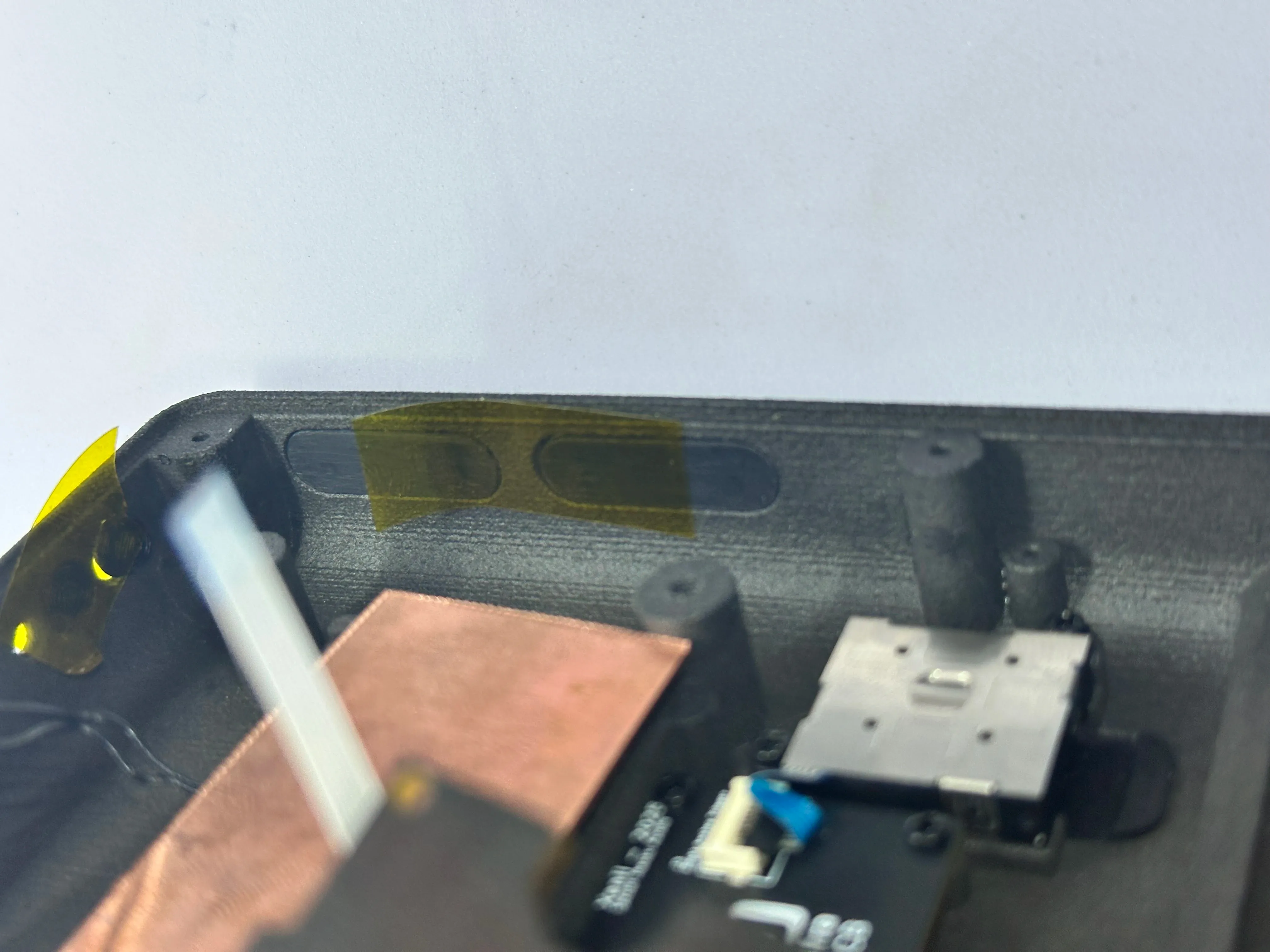
- Place the
BrightnessandVolumerockers into their slots. Each rocker has a notch, so note the orientation. A small piece of tape can be used to keep them there.
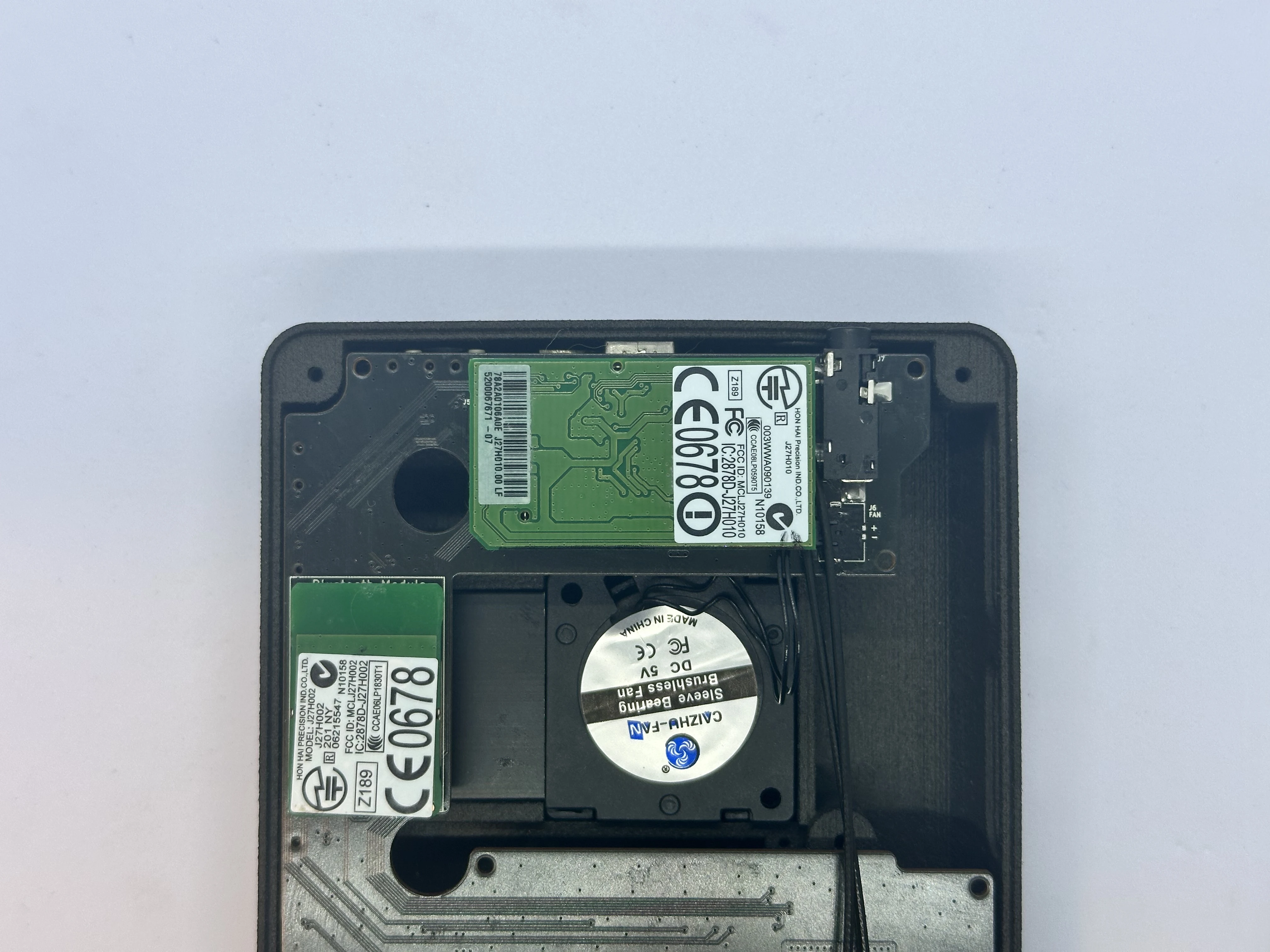
- Take the Bluetooth module that was retrieved from the Wii’s PCB and insert it into the gray connector on the bottom of the Main PCB. The module should have a small cushion to keep it adhered to the Main PCB. If the cushion ripped or is missing, a strip of double sided tape works instead.
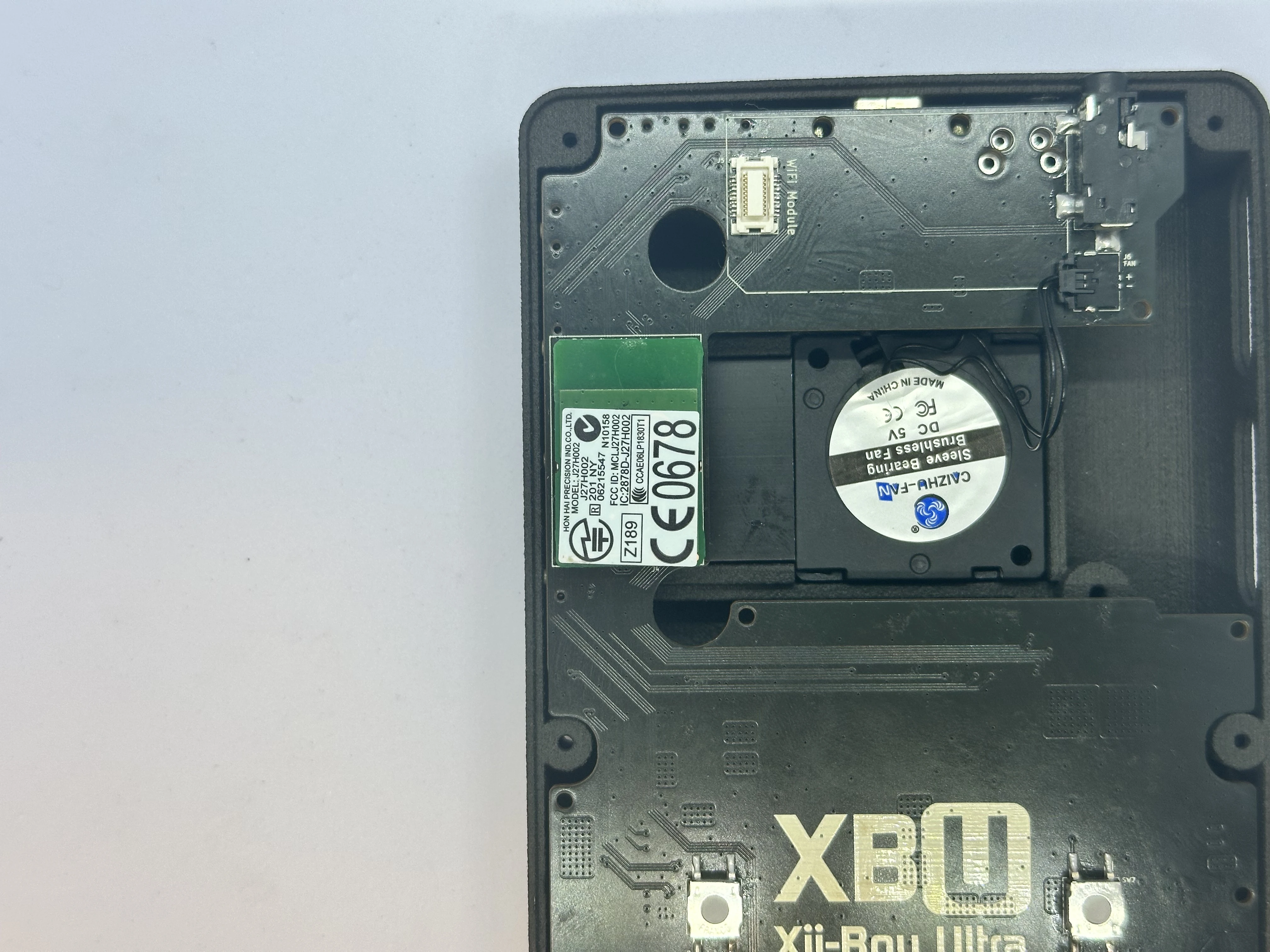
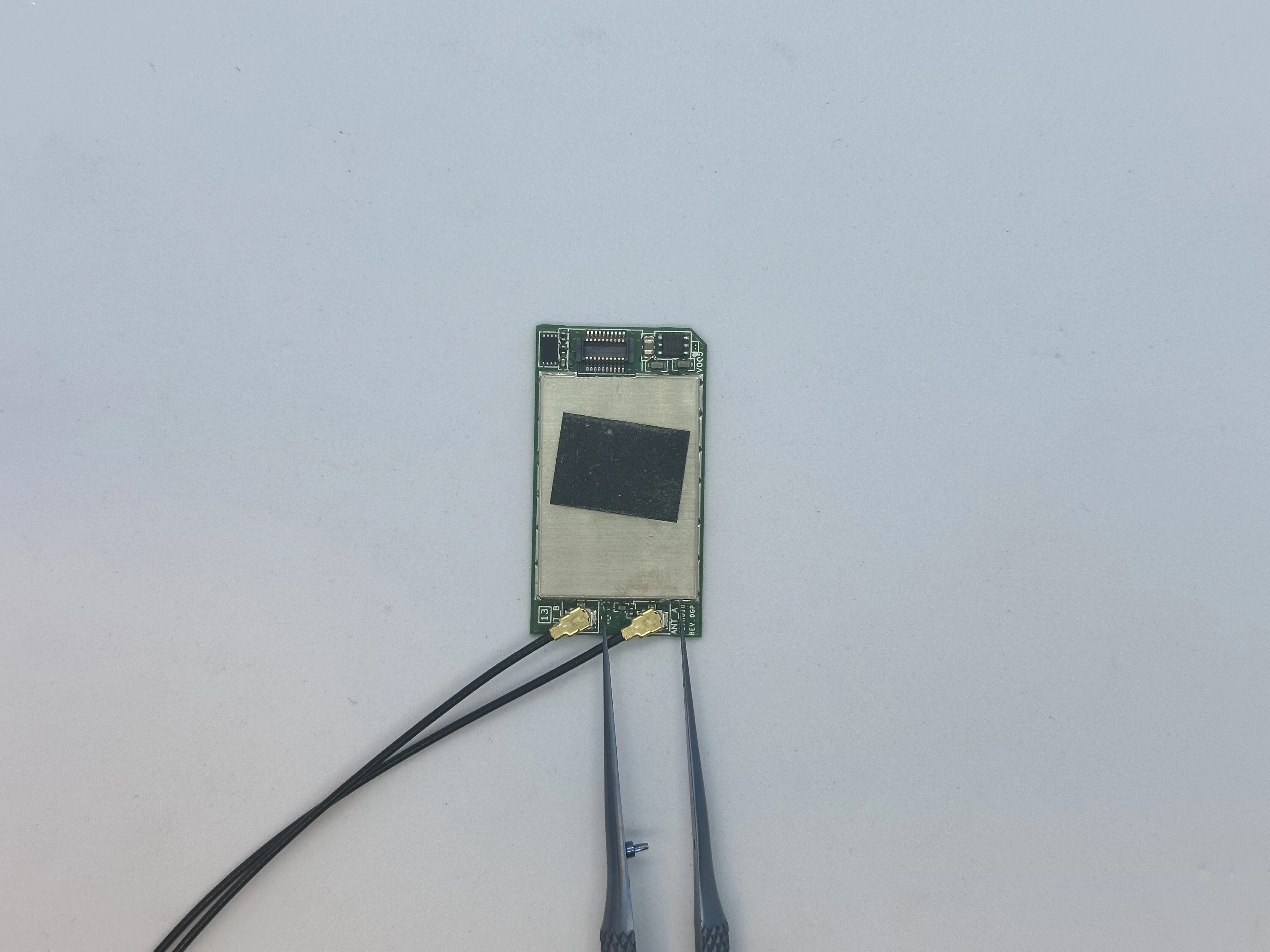
- Take the Wi-Fi module that was retrieved from the Wii’s PCB and attach the Wi-Fi antenna connectors. Insert the Wi-Fi connector into the white connector on the bottom of the Main PCB. Ensure the Wi-Fi antenna cables are facing toward the top of the shell.
Upper Layer
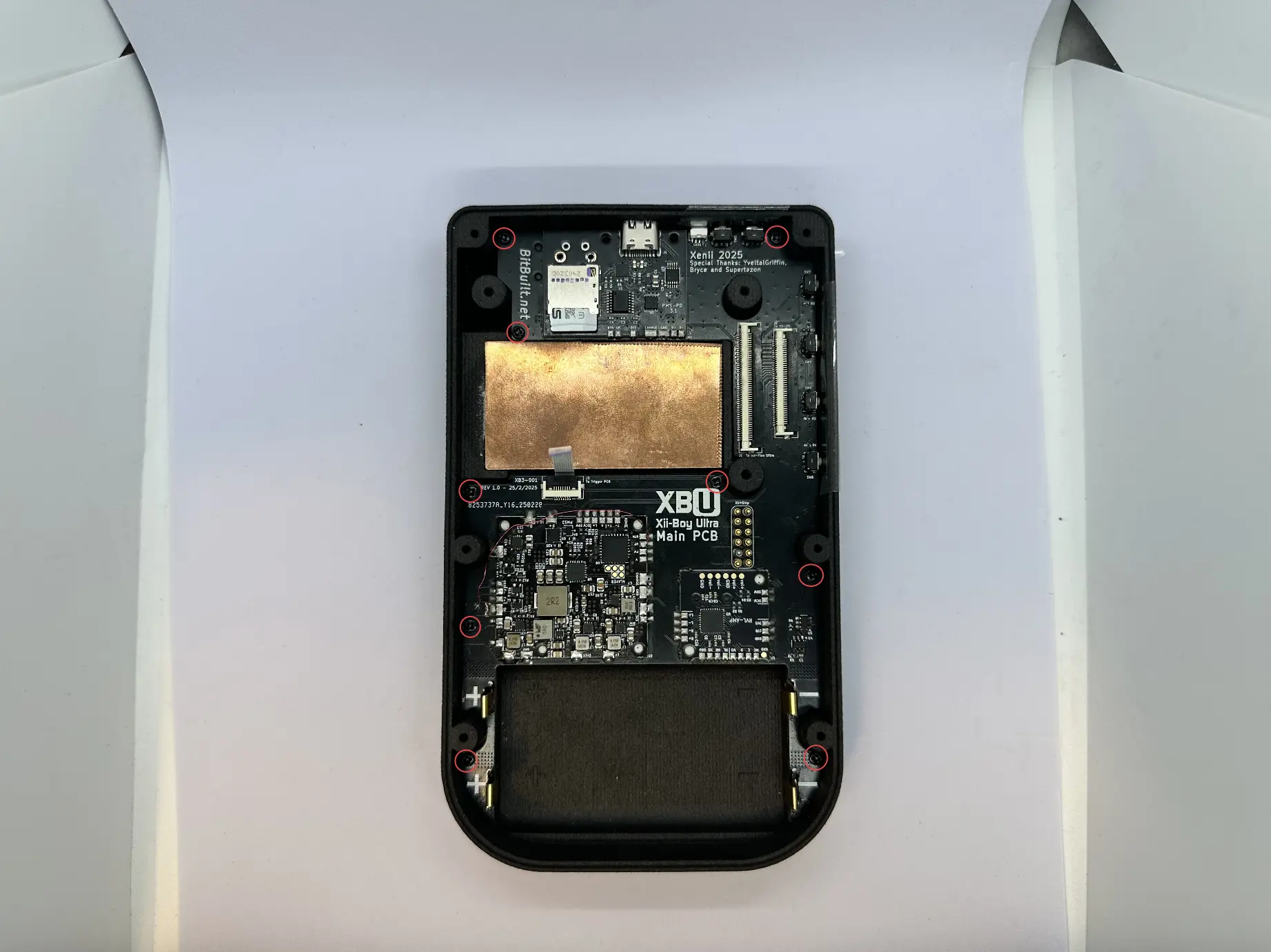
- Insert the Main PCB into the shell at a
45°angle. The USB-C port and Headphone Jack will slot nicely into place. While lowering the PCB, ensure the Trigger PCB flex cable and Fan PicoLock (not pictured) pass into the Upper Layer.
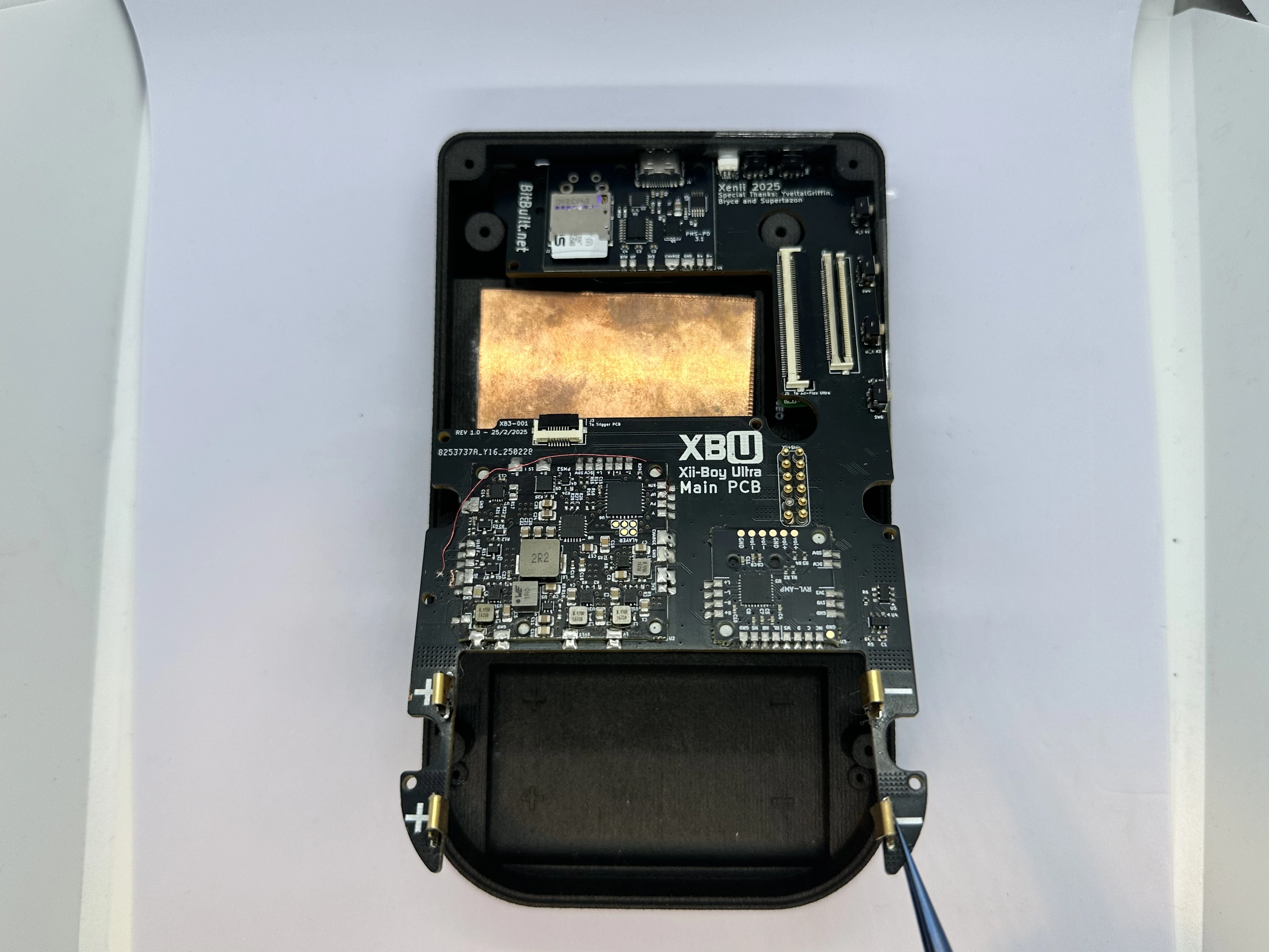
- If everything was performed properly, the Main PCB will sit flat against the shell. If not, lift it and try again, ensuring no cables were pinched underneath. Then, screw nine
4mmPhillips screws into place.
- Pull directly up and remove the tape covering the
Power,BT Sync,Brightness, andVolumebuttons.
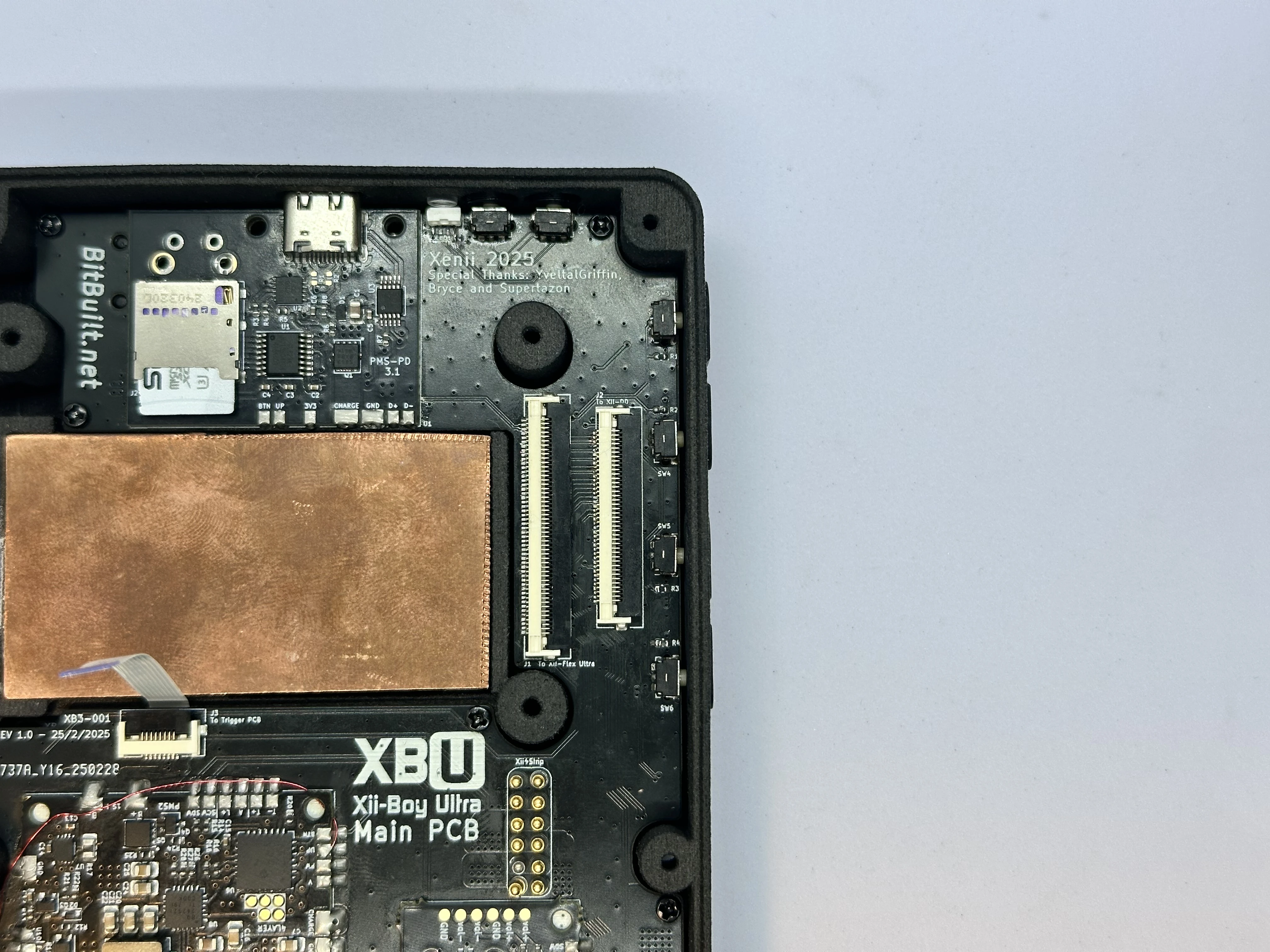
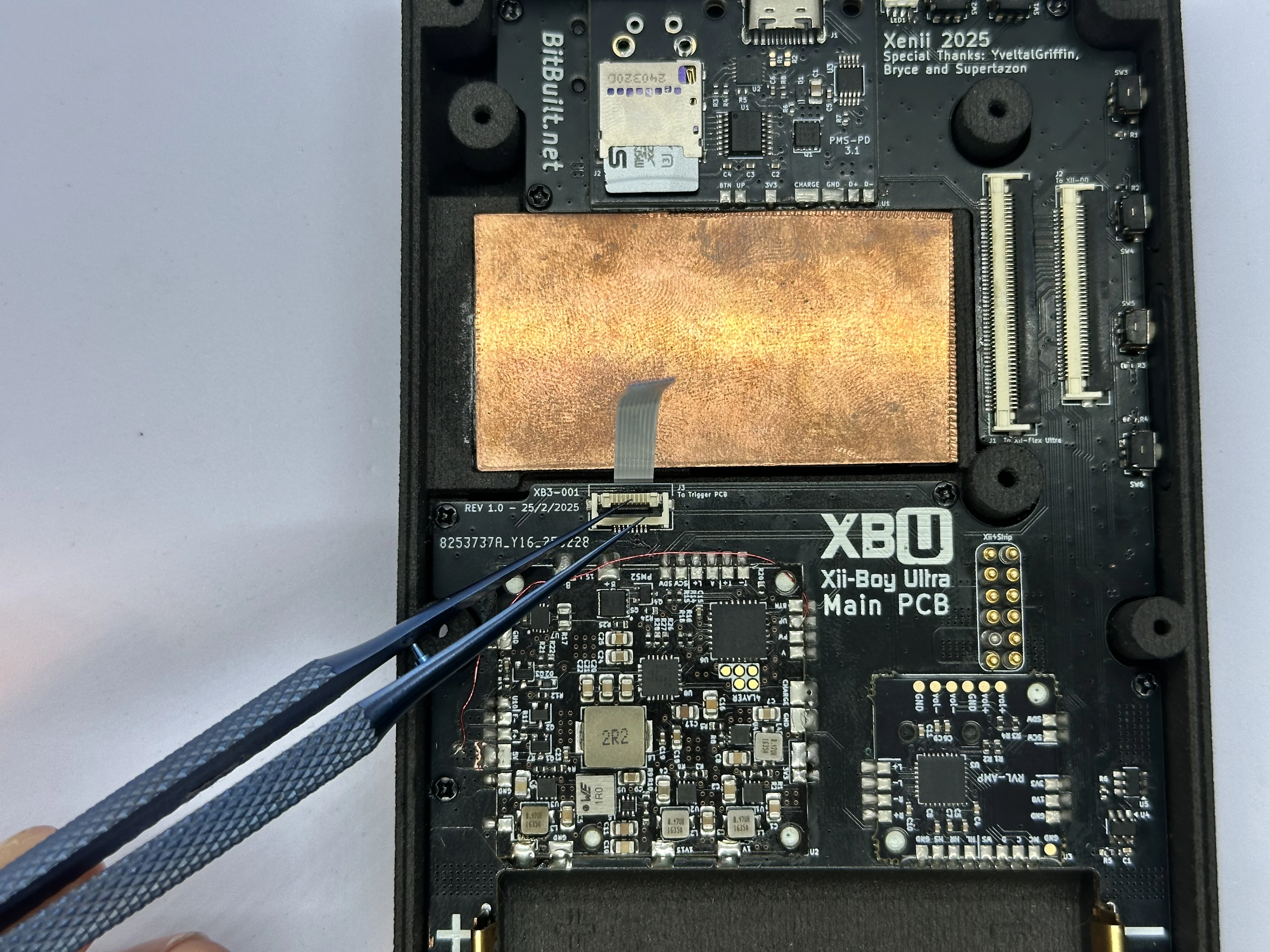
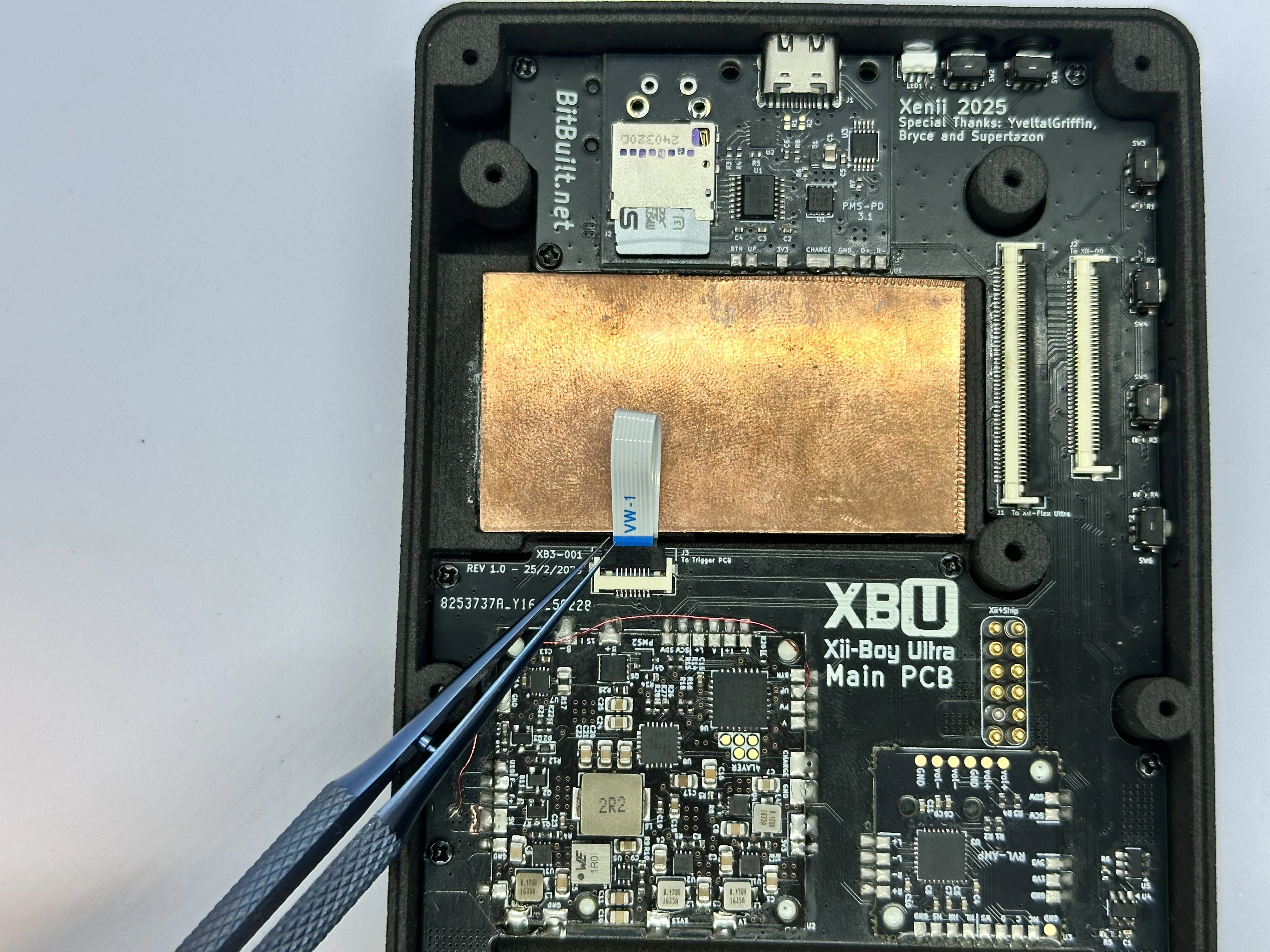
- Unlock the 8 Pin Trigger PCB ZIF connector. Bend the FFC as pictured and insert it into the ZIF connector. Lock the connector, and bend the cable over the RVL-PMS2.
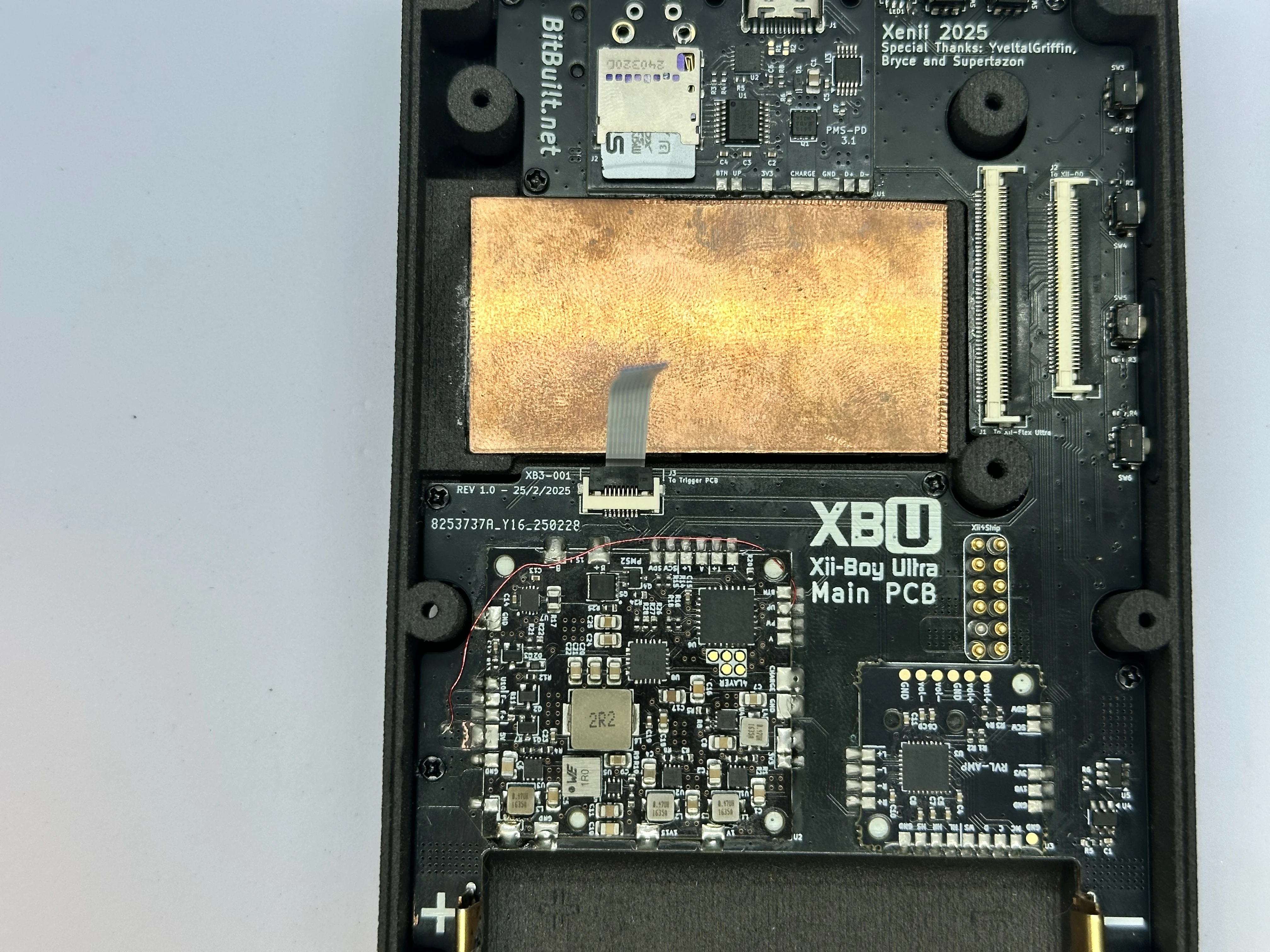
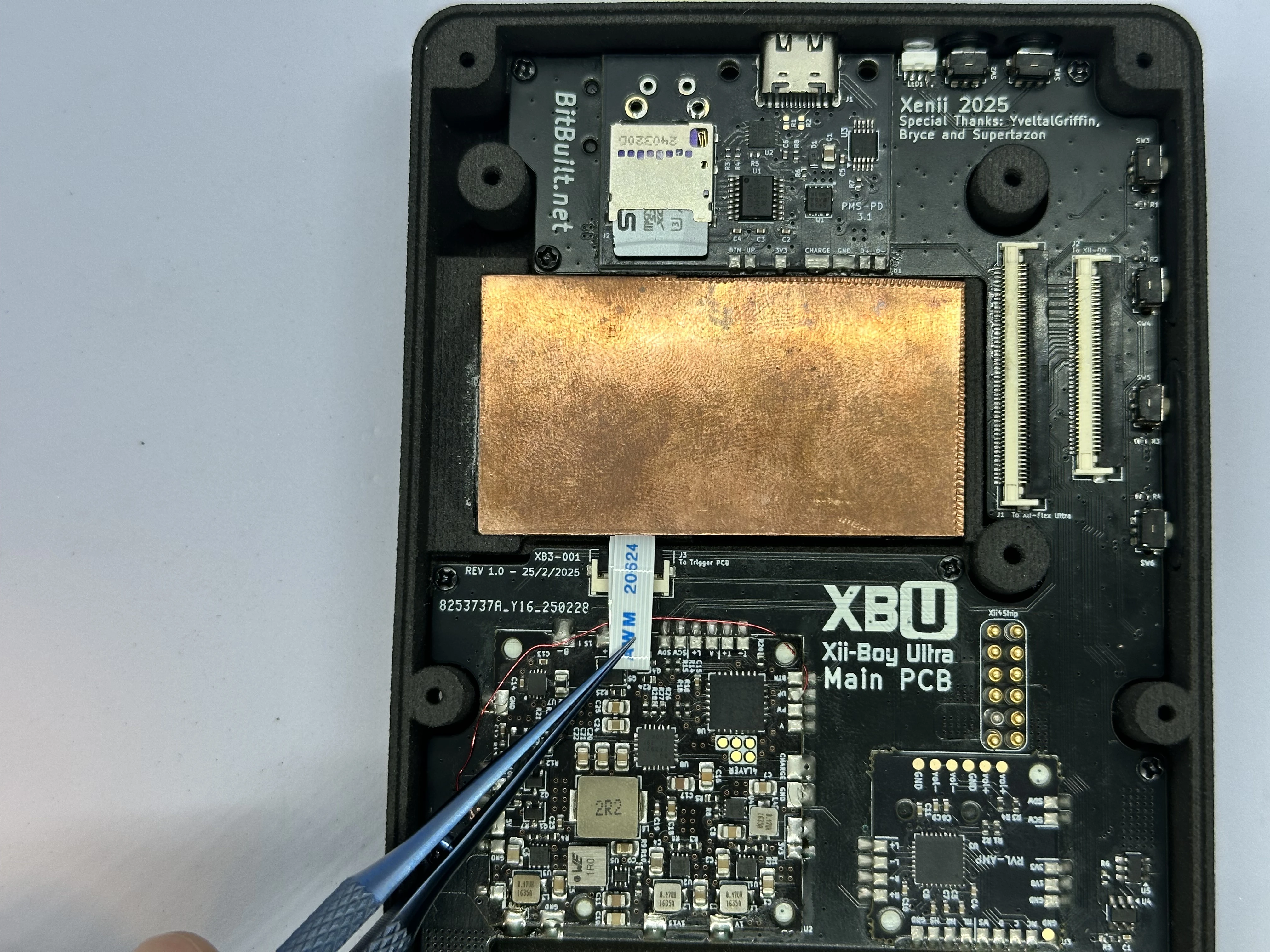
- Connect the Fan’s male PicoLock connector to the Main PCB’s Female connector located in the upper left corner of the board. Tuck the excess cable to the side so it avoids the copper plate.
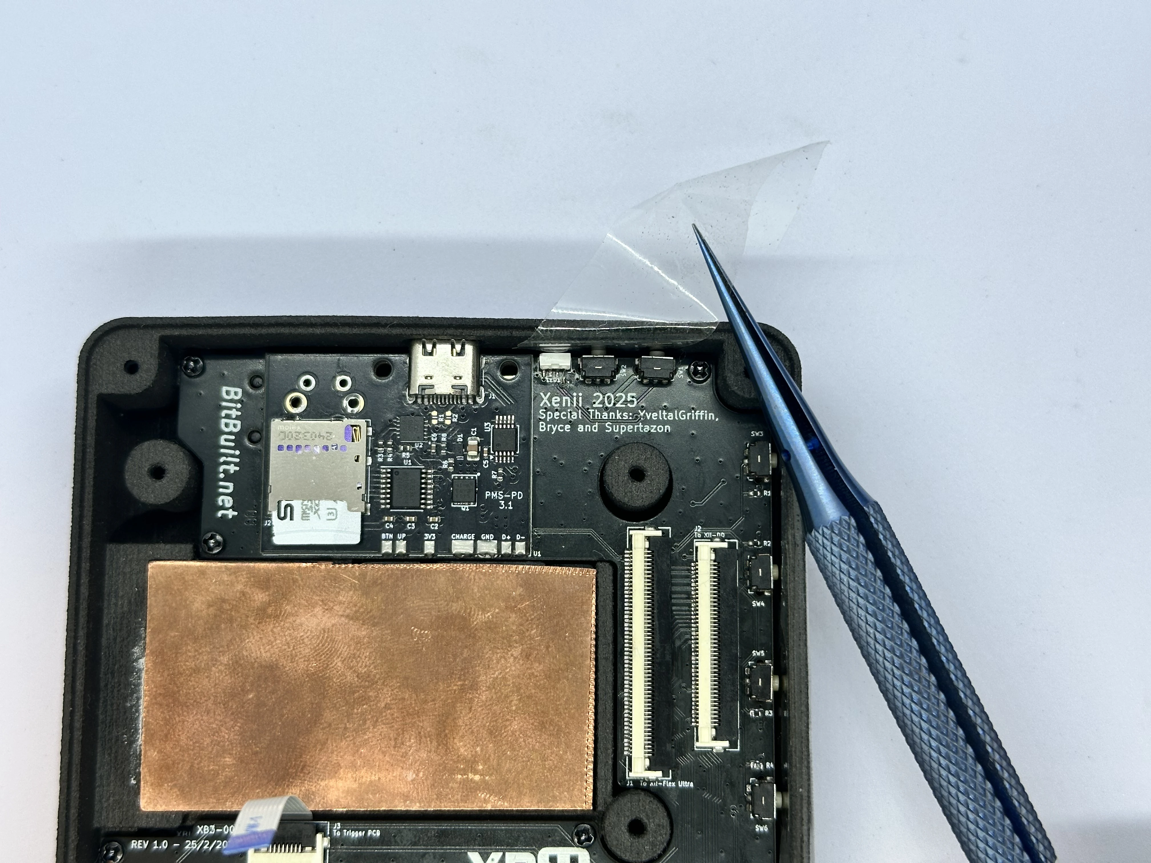
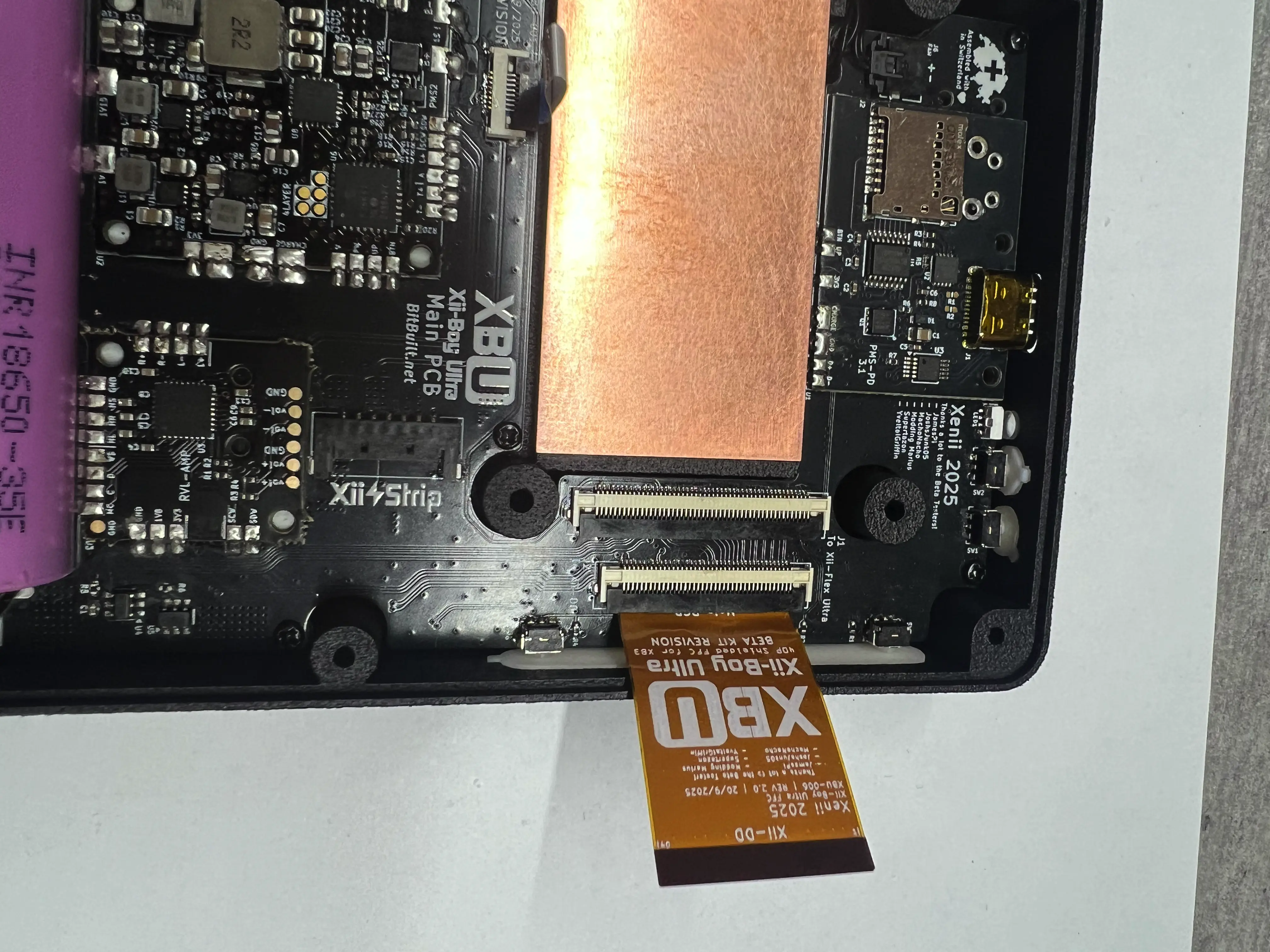
- Take the 40p Shielded FFC (XBU-007) and bend the tips of the stiffener. Note the orientation, as the flex can only be installed one way. If it is inserted in the incorrect orientation, it will cause a short between 3.3v and GND.
- Unlock the 40 Pin Xii-DD ZIF connector. Bend the FFC as pictured and insert it into the ZIF connector. Lock the connector.
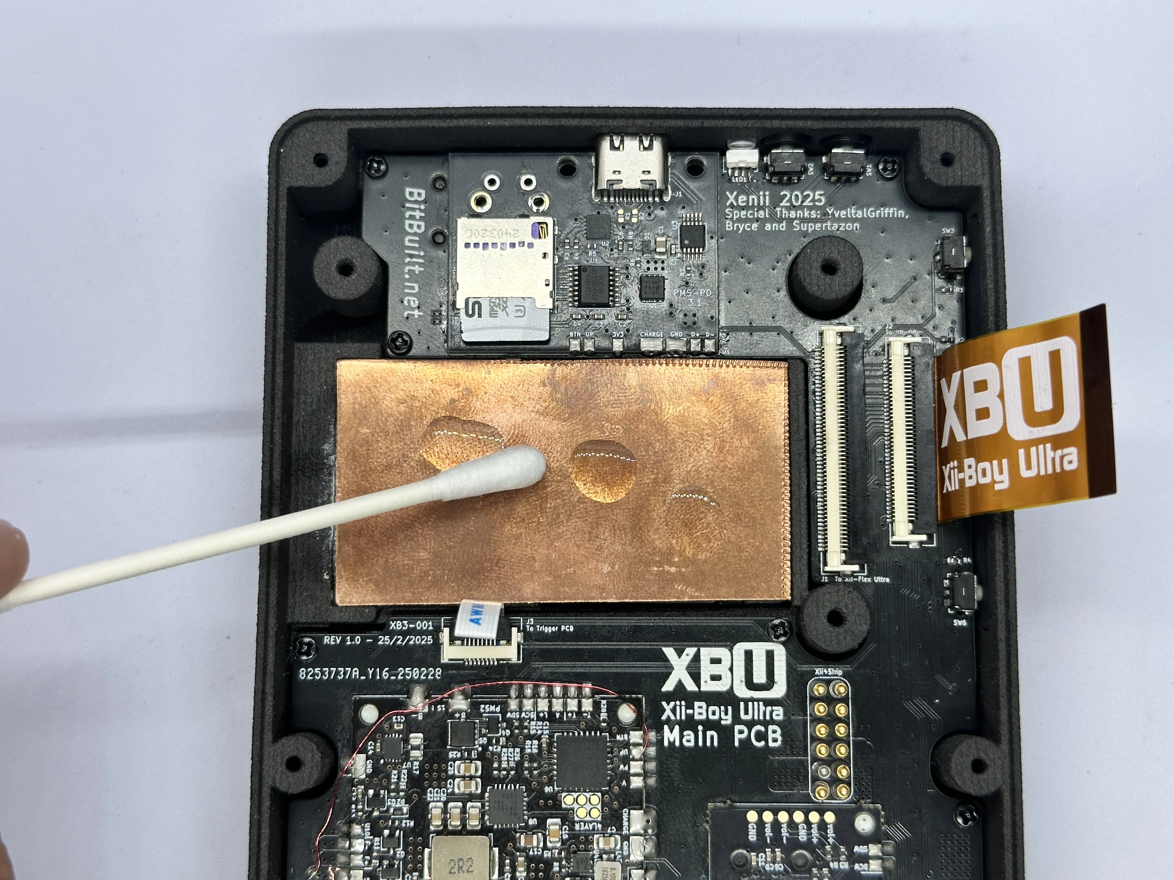
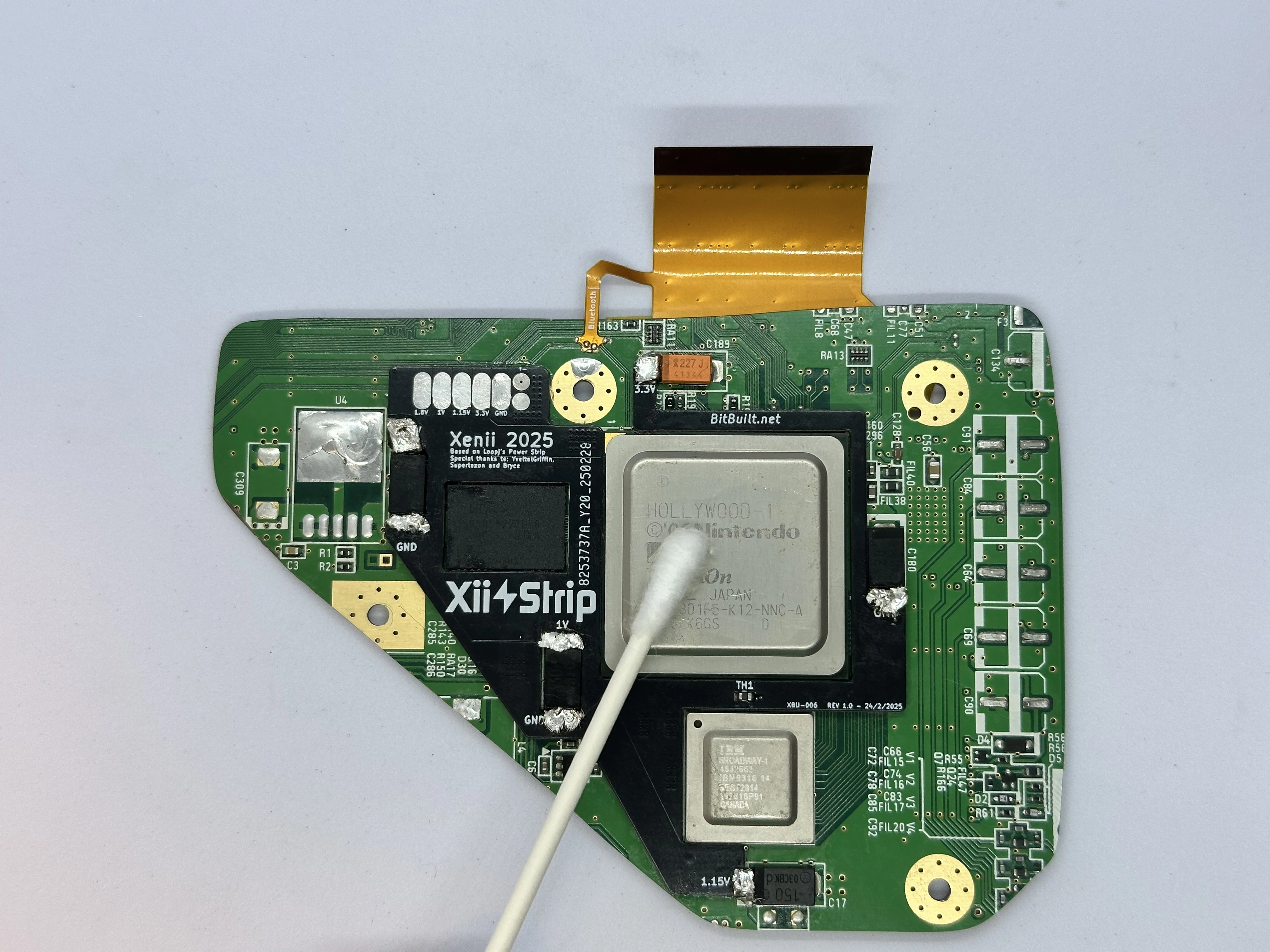
- Apply a few drops of 99% isopropyl alcohol onto the copper plate. A Q-Tip can then be used to wipe it up and clean off the surface. Repeat for the Hollywood and Broadway chips on the Wii’s PCB.
- Check the voltages of both 18650 battery cells with a multimeter. Ensure they are within ~0.1v of each other. Insert each of the batteries into the holders at the bottom of the shell, noting the orientation (+ on the left and - on the right). Check that there is a solid connection between the battery terminals and the Main PCB battery tabs.
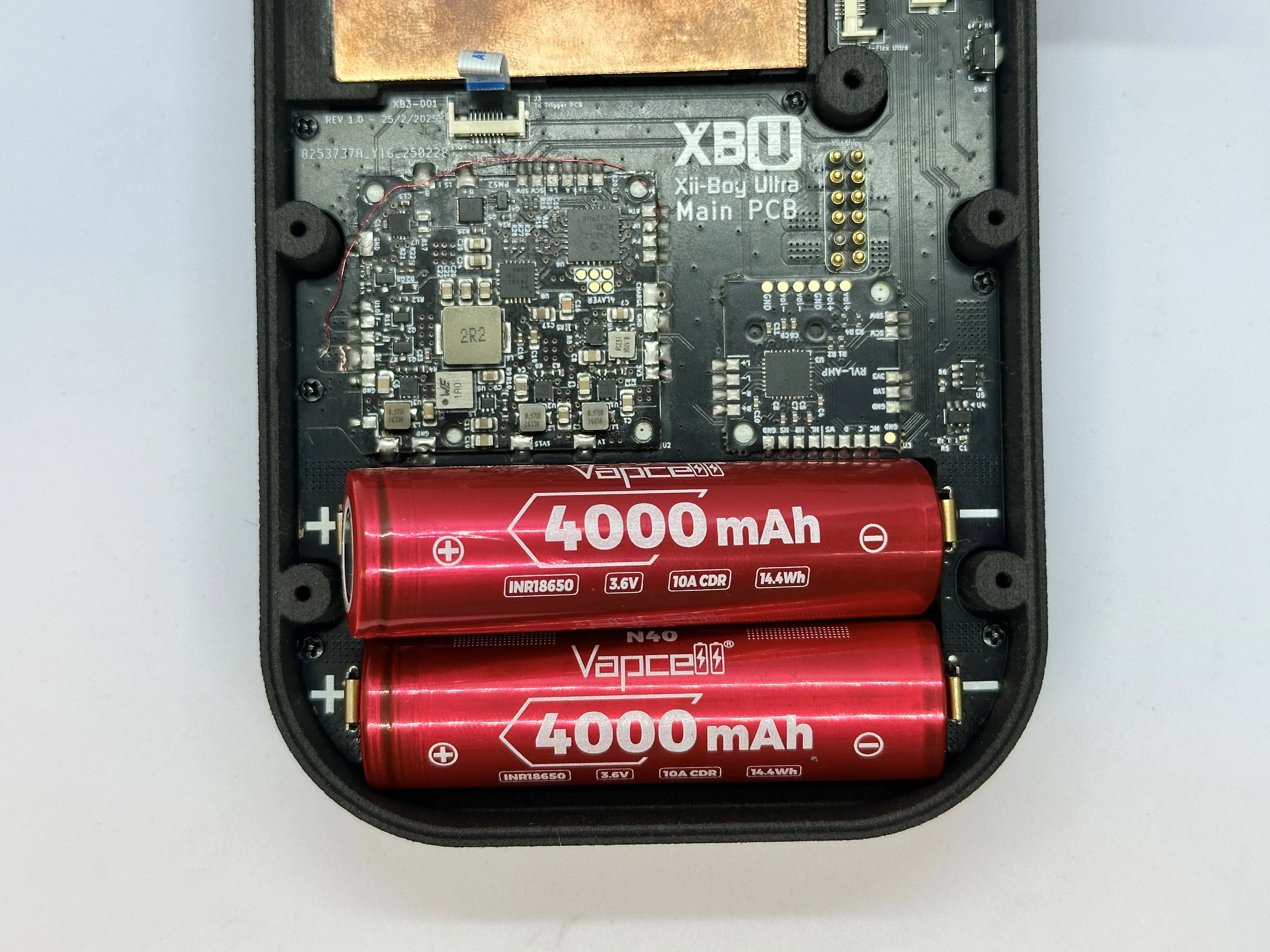
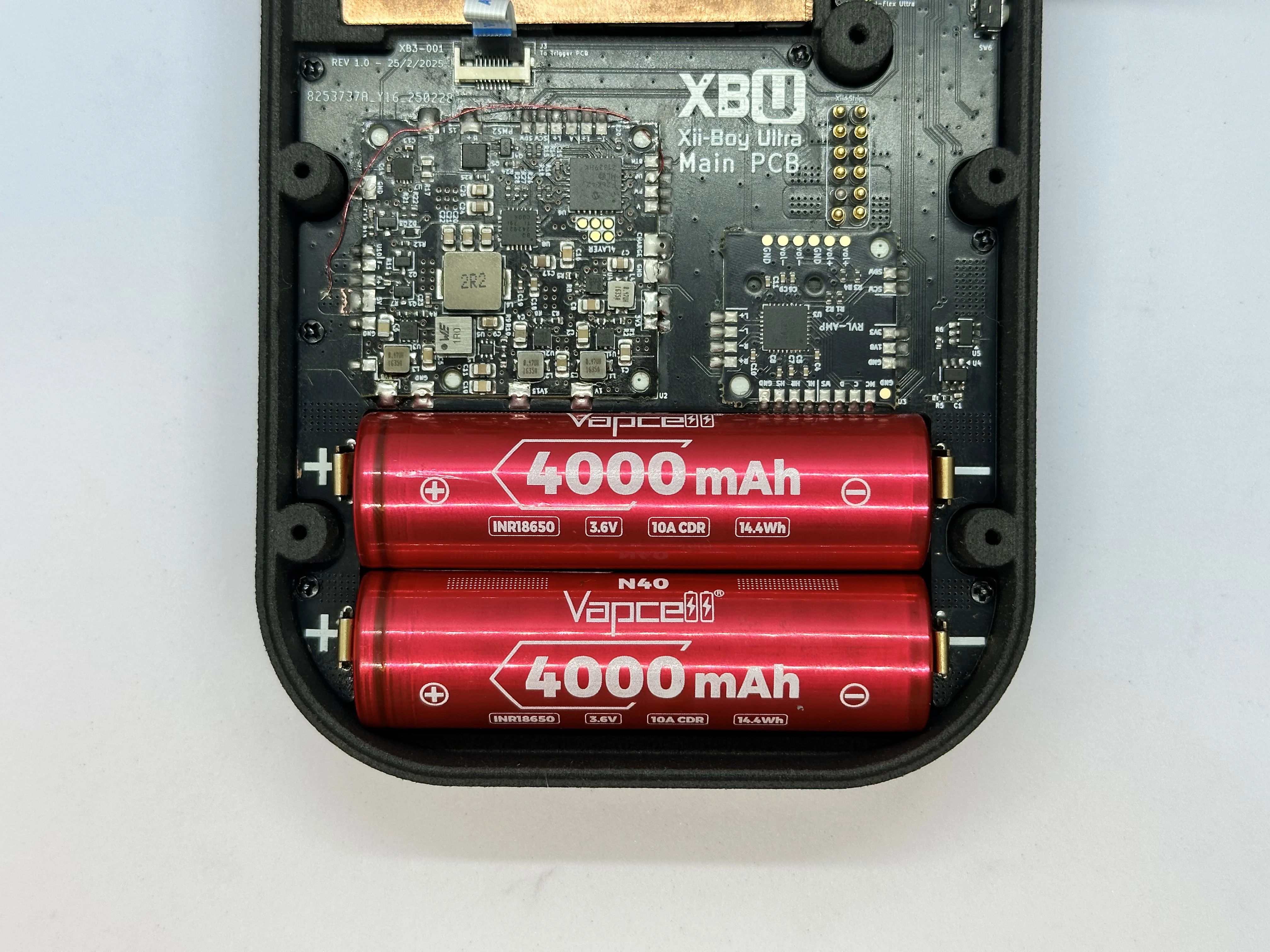
IMPORTANT: Battery Safety
The orientation of the batteries is crucial, inserting them backwards can cause permanent damage to the RVL-PMS2 and the rest of the Xii-Boy Ultra. Connecting two batteries in parallel at drastically different voltages can cause a fire in the worst case scenario, and damage the battery capacity at best. If the batteries are not within ~0.1v of each other, charge one until it is equivalent.
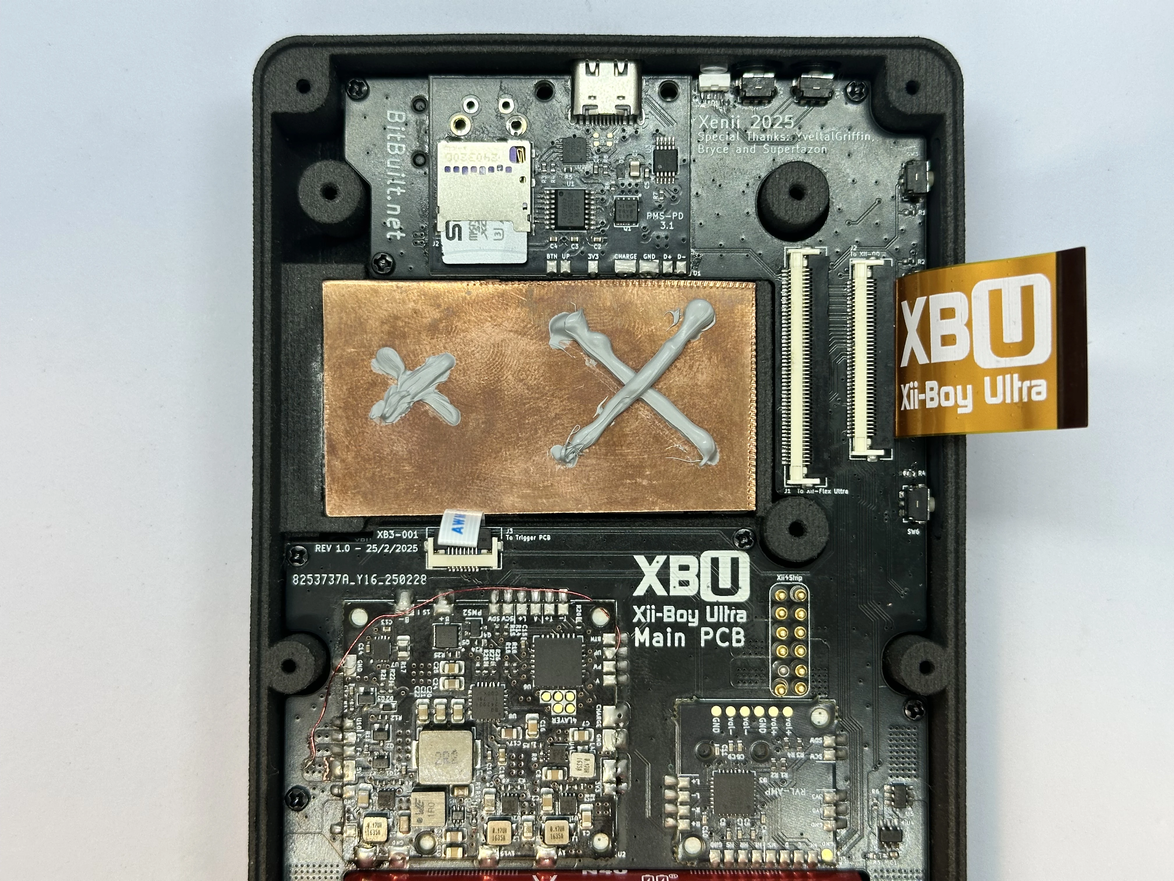
- Apply thermal paste to the copper plate in two
Xshapes. One largeXfor Hollywood, and a smallerXfor Broadway.
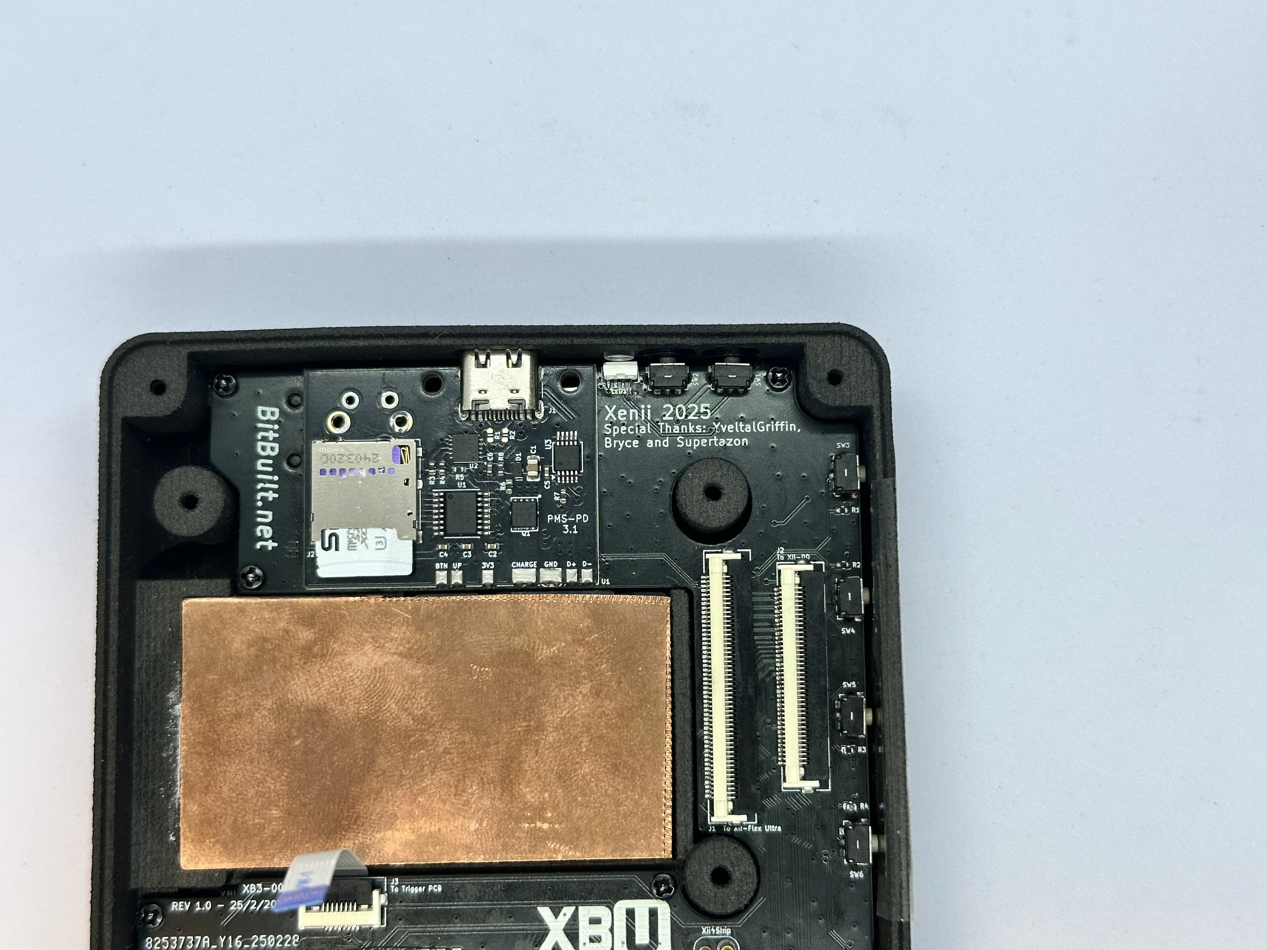
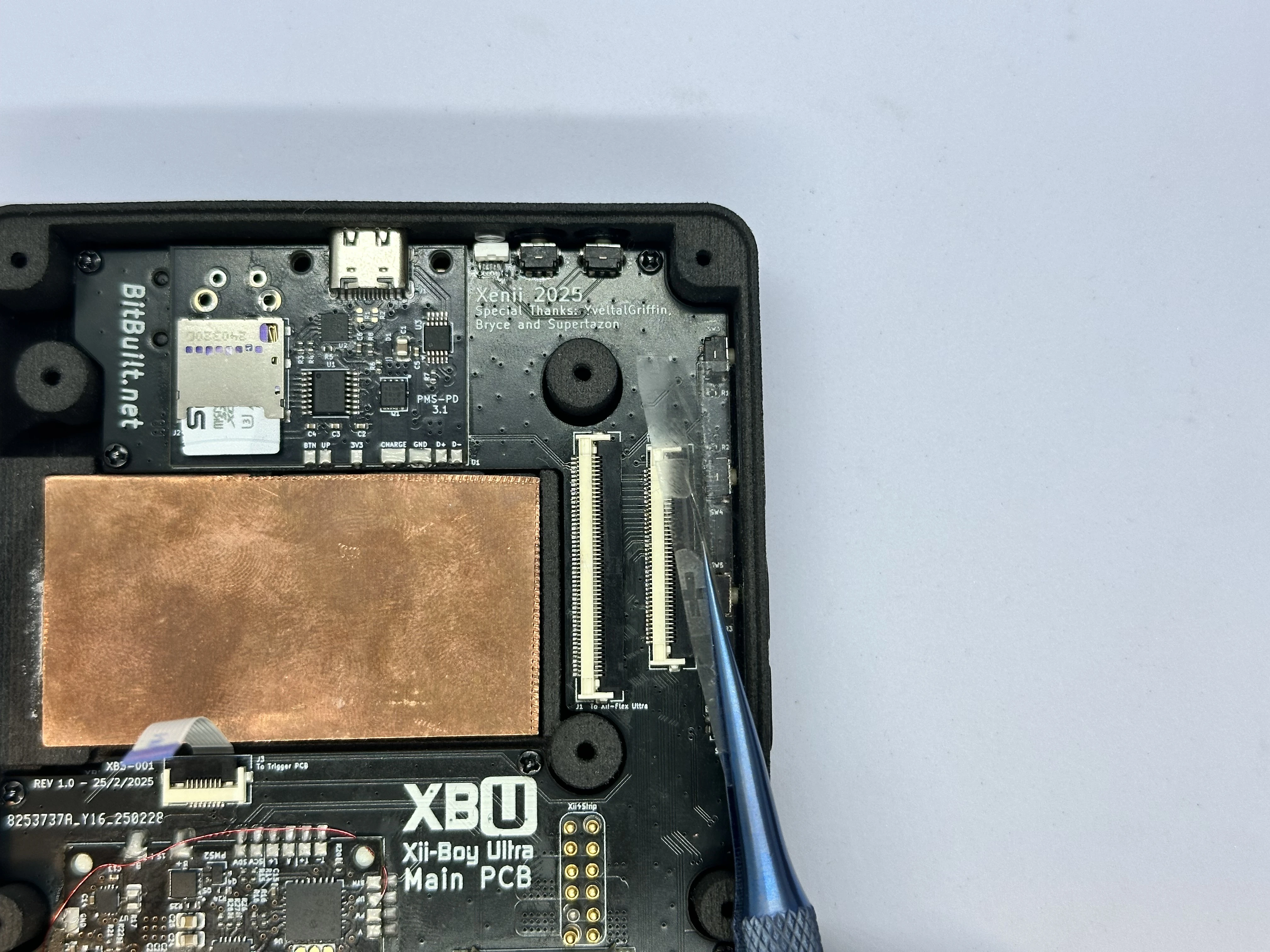
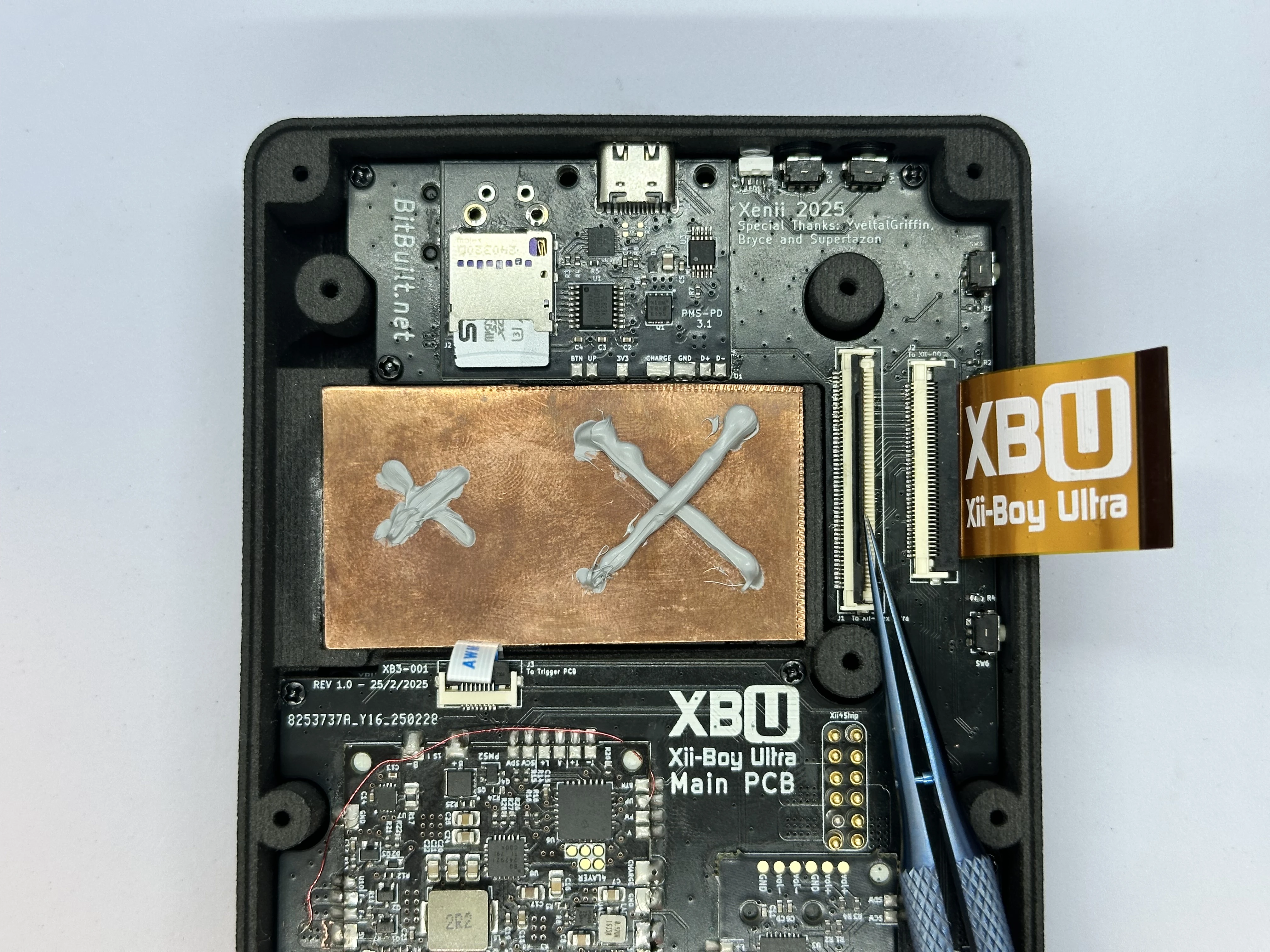
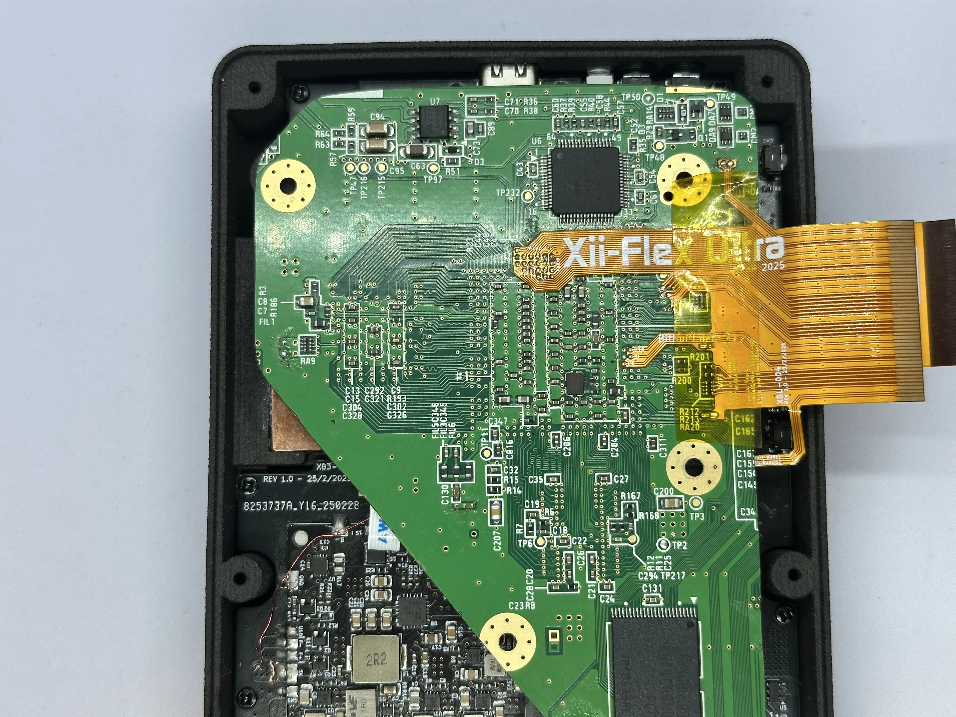
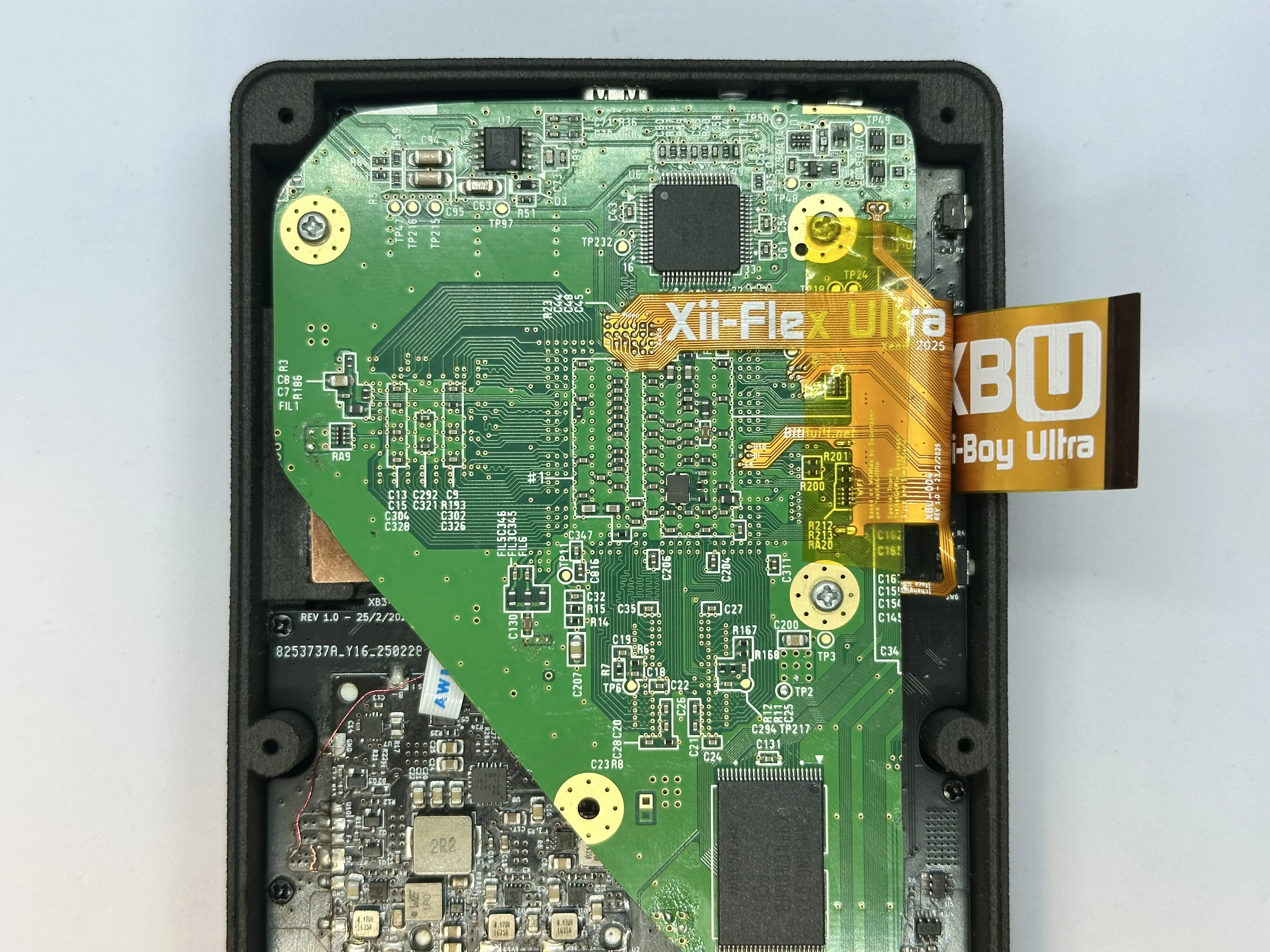
- Unlock the 50 Pin Xii-Flex Ultra ZIF connector. Insert the Xii-Flex Ultra into the ZIF connector and lock it.
- Insert the PicoLock power connector into the Main PCB and the Xii-Strip.
INFO
This is not pictured, as it was added in a later revision. It replaces the pogo pins in the images.
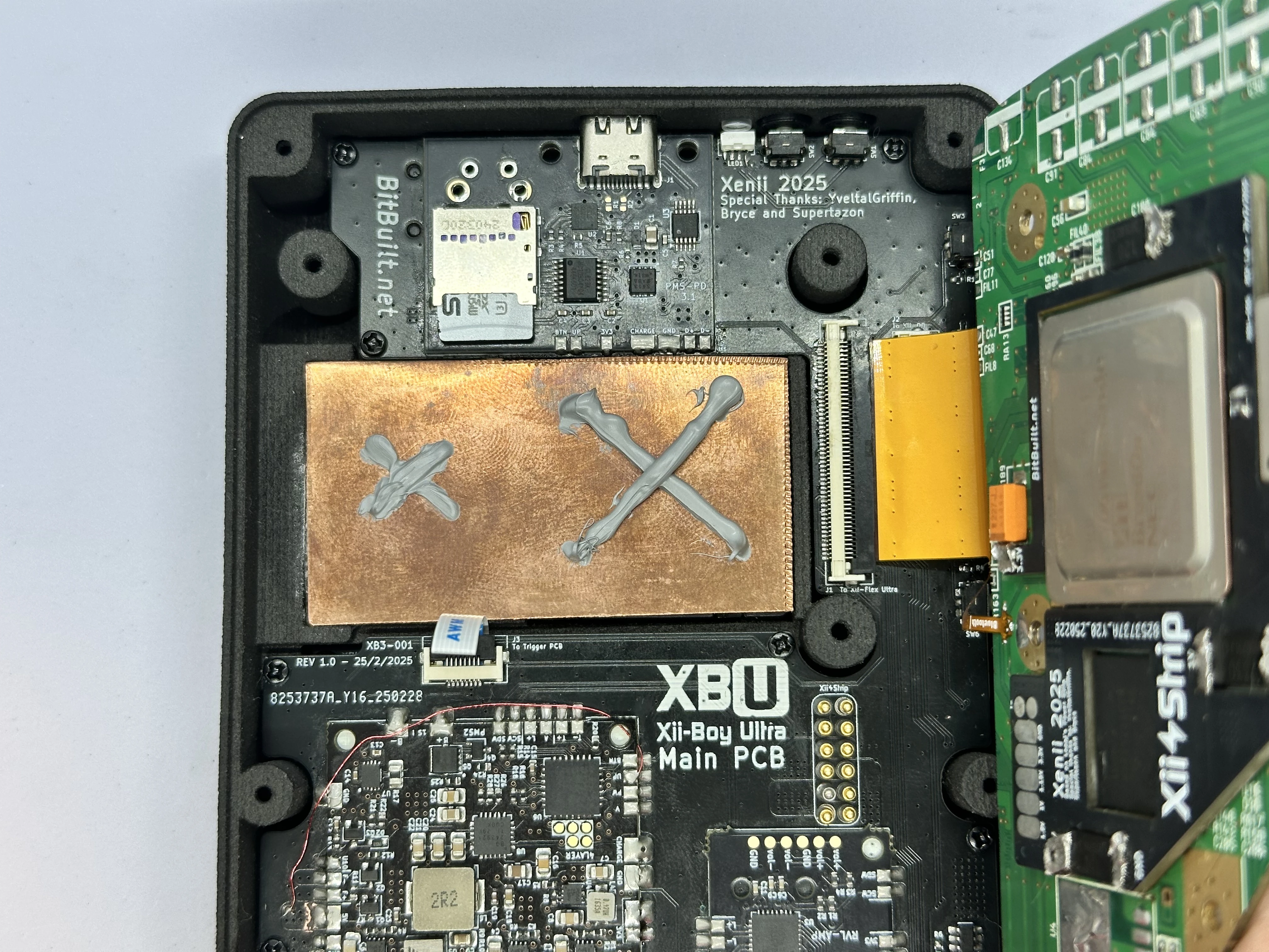
- Fold the Wii over the copper plate and press down firmly to spread the thermal paste. Align the screw holes on the Wii with the three screw posts on the bottom shell. Use three silver
7.3mmPhillips screws from the Wii’s motherboard cover (https://www.ifixit.com/Guide/Nintendo+Wii+Heat+Sink+Replacement/3458#s16575) to fasten the trimmed Wii in place.
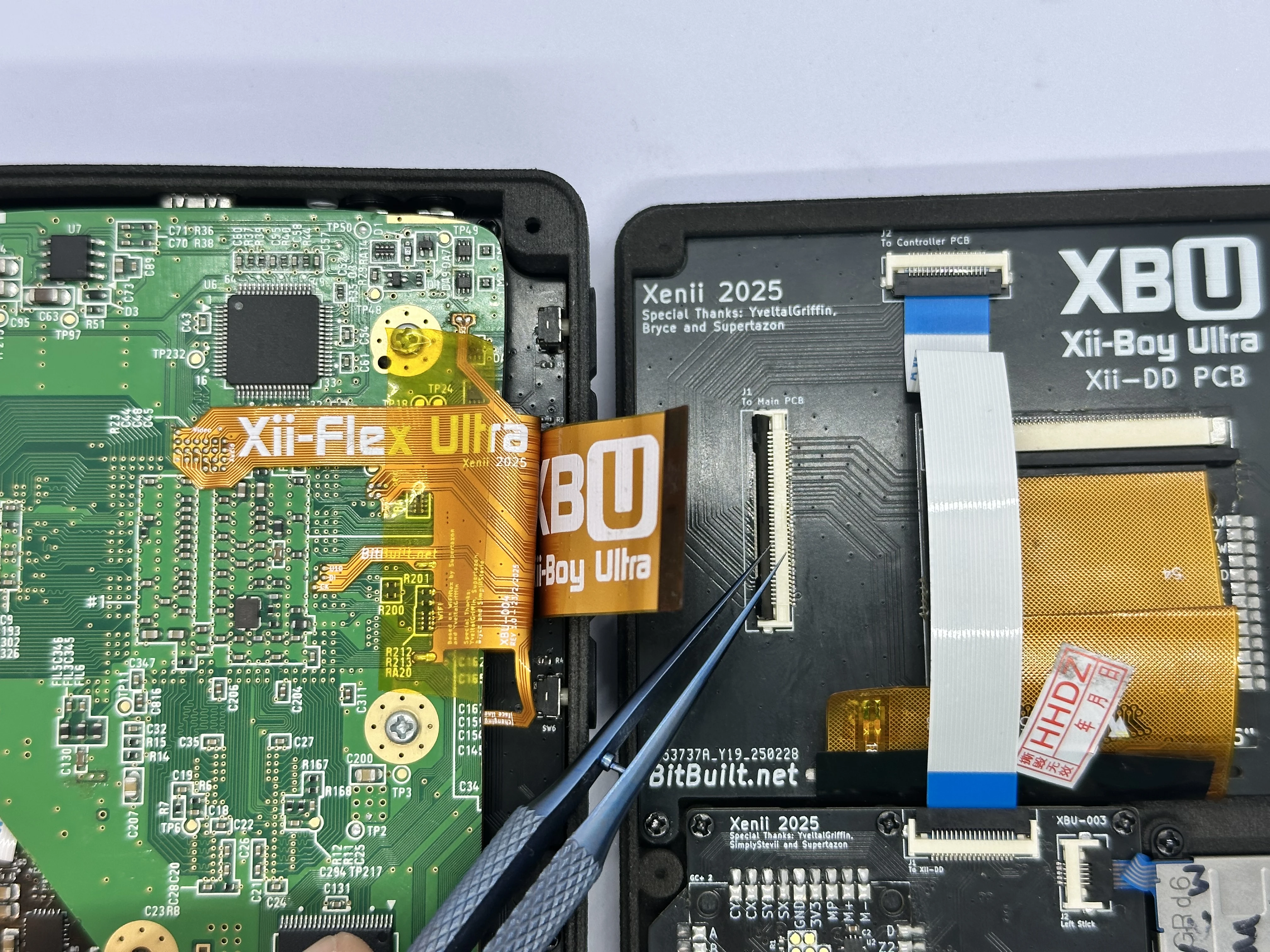
- Unlock the 40 Pin Main PCB ZIF connector on the Xii-DD PCB. Insert the 40 Pin Shielded FFC and lock the connector.
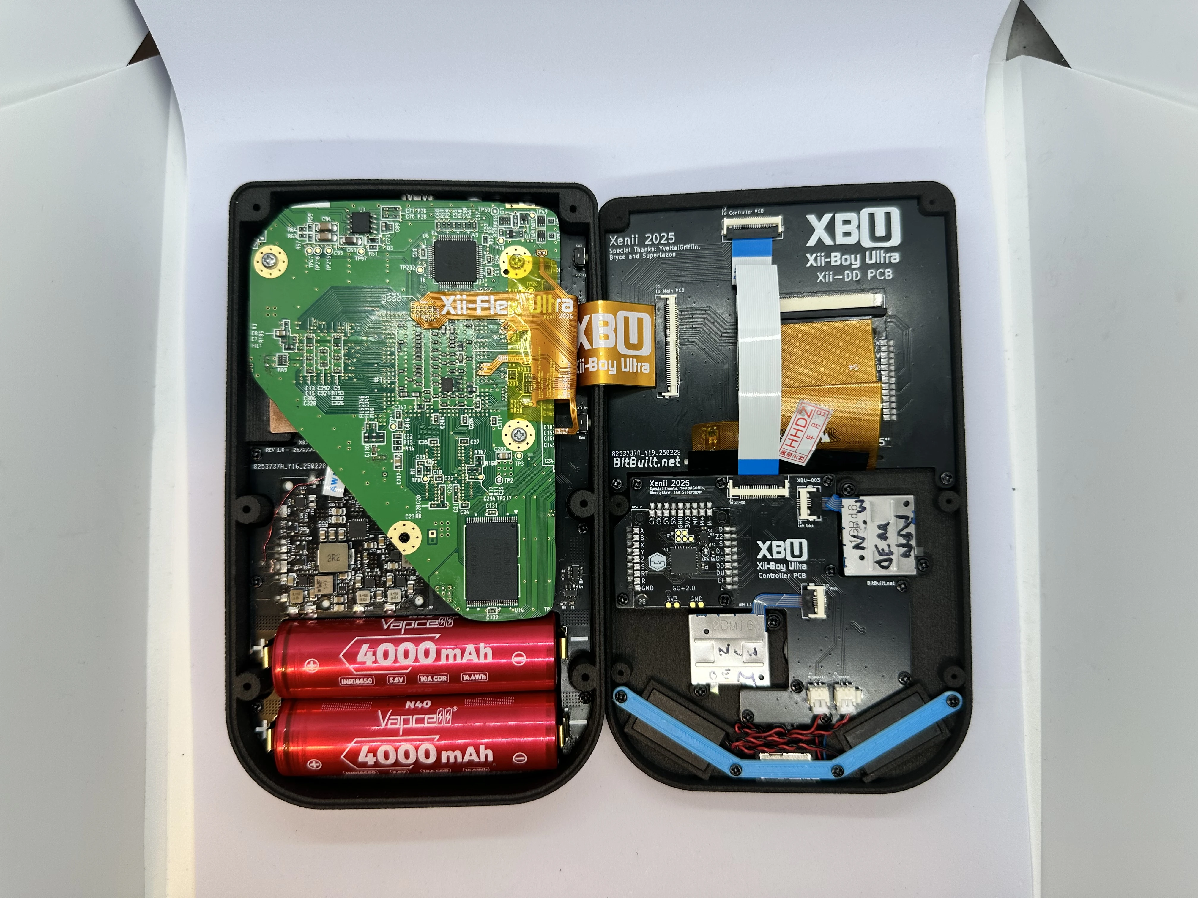
- Close both halves and connect them with six
6mmPhillips screws. The screwholes in the bottom shell are recessed, so a screwdriver with a long tip is required.
The Xii-Boy Ultra Assembly is now complete. Proceed to RVLoader setup.