Wii Trimming
The reason Wii portables of this size are possible is because of motherboard trimming. The Wii is the perfect trim candidate. In almost any computer system, there are a few crucial components: the CPU, GPU, RAM, and NAND. All four of those components sit next to each other on the Wii, and they are what define our trim lines. The Xii-Boy Ultra uses a trim which just goes around the core components without relocating them. This trim is one of the simplest, but that doesn’t mean it’s easy. Go slow and follow each step carefully. Cutting a critical component or trace can render the Wii inoperable.
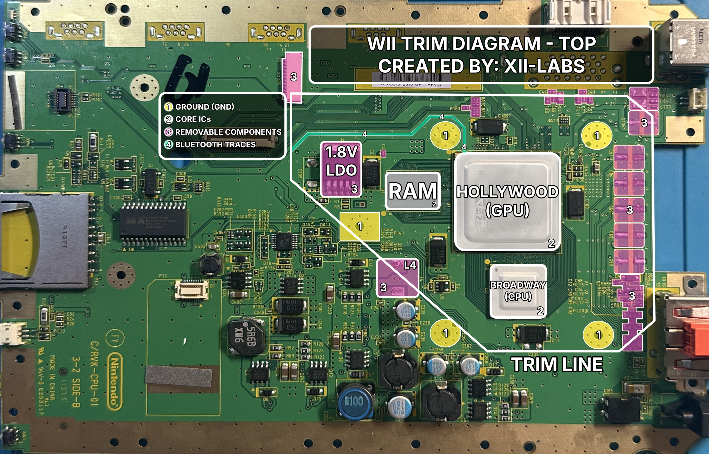
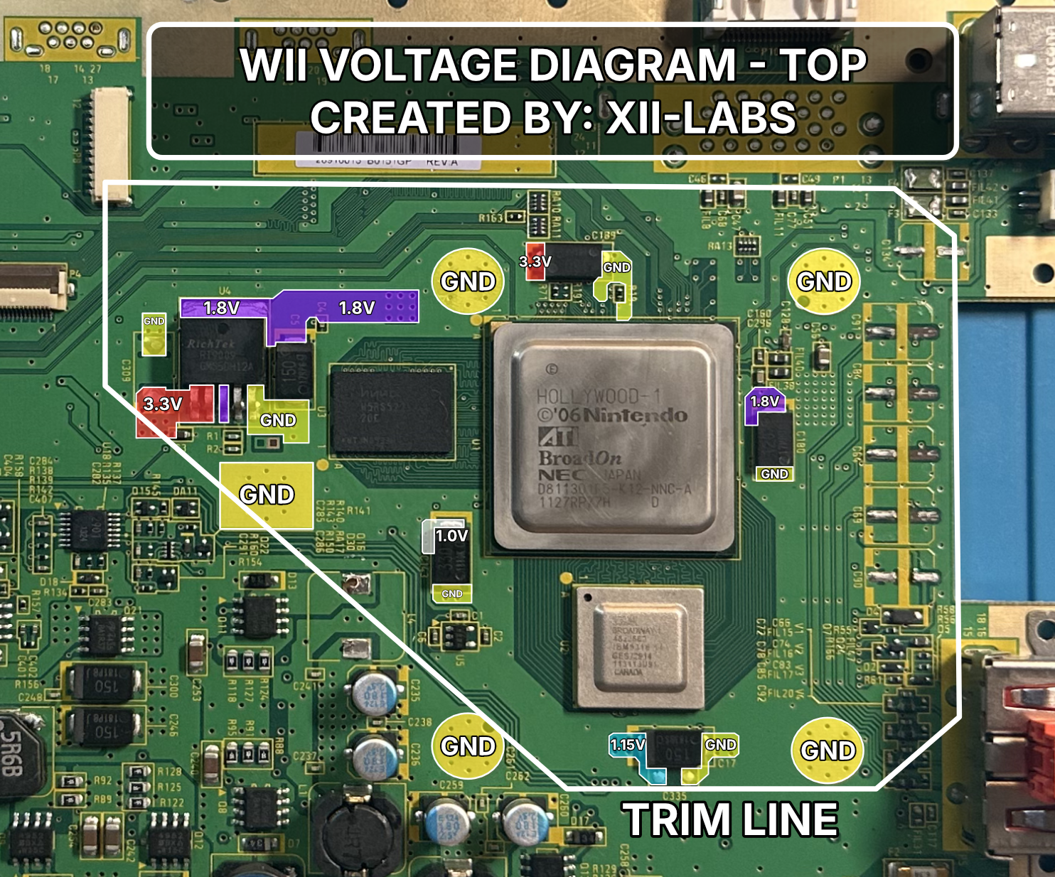
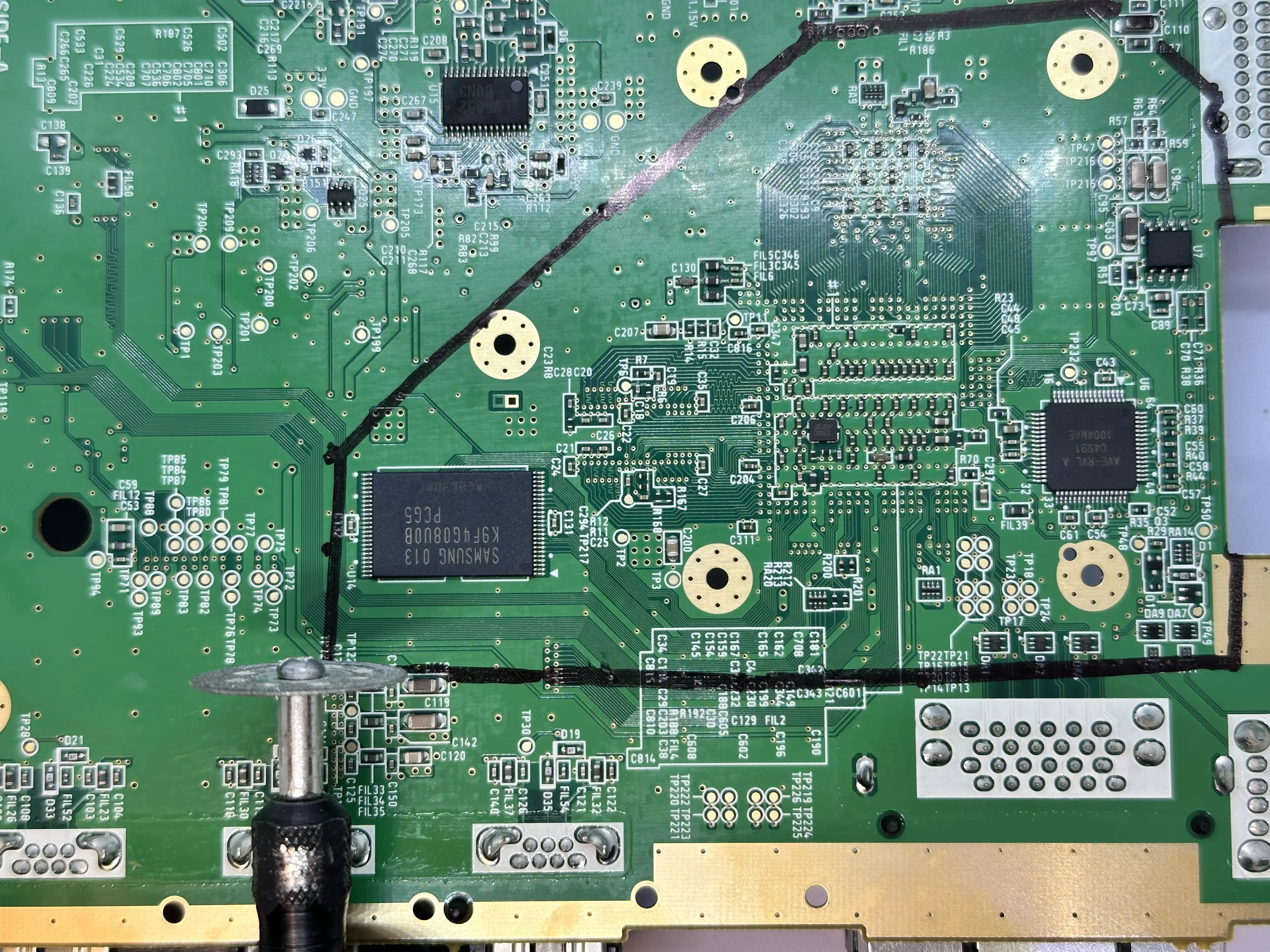
Trimming Diagrams
These diagrams contain annotated images of the bare Wii motherboard. Use them as a reference when drawing trim lines, removing components, or checking important traces.

Trimming Steps
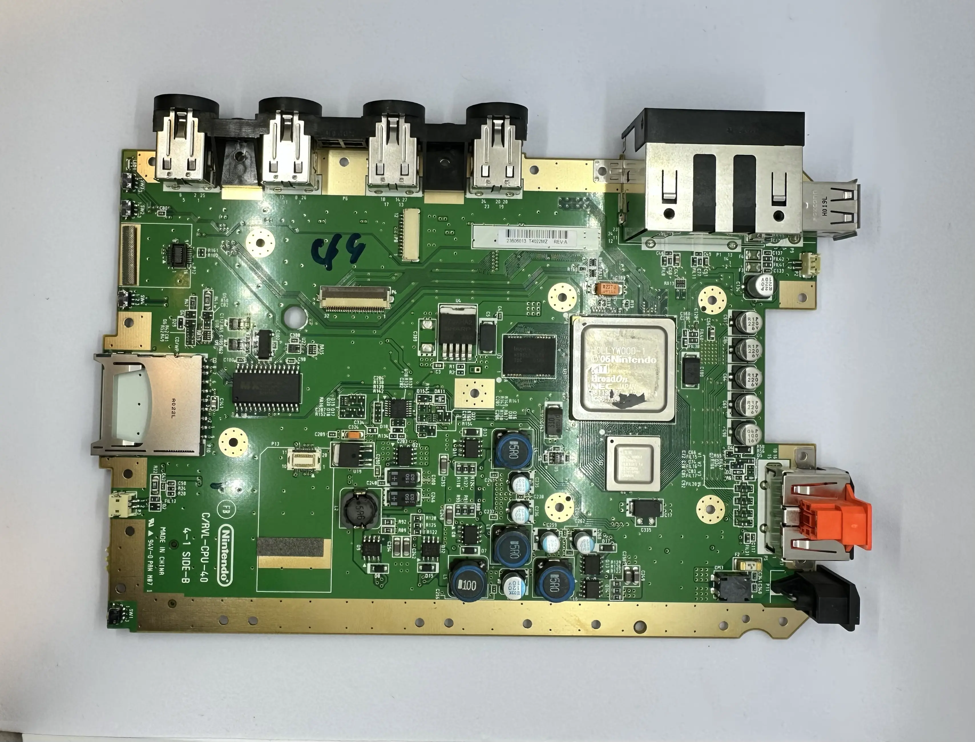
- Disassemble the console down to the bare motherboard. There are many great tutorials out there; the recommended one is by iFixit.
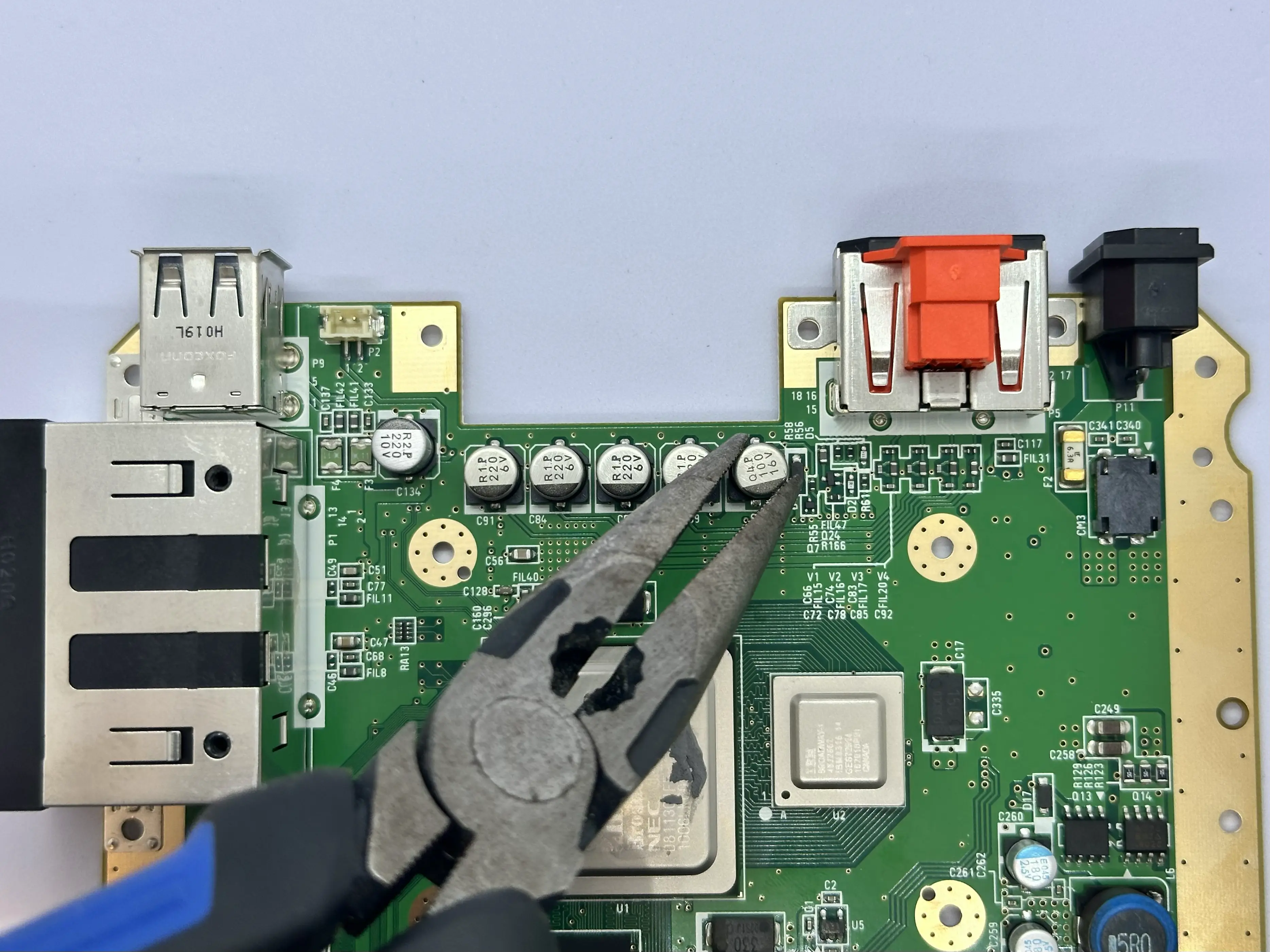
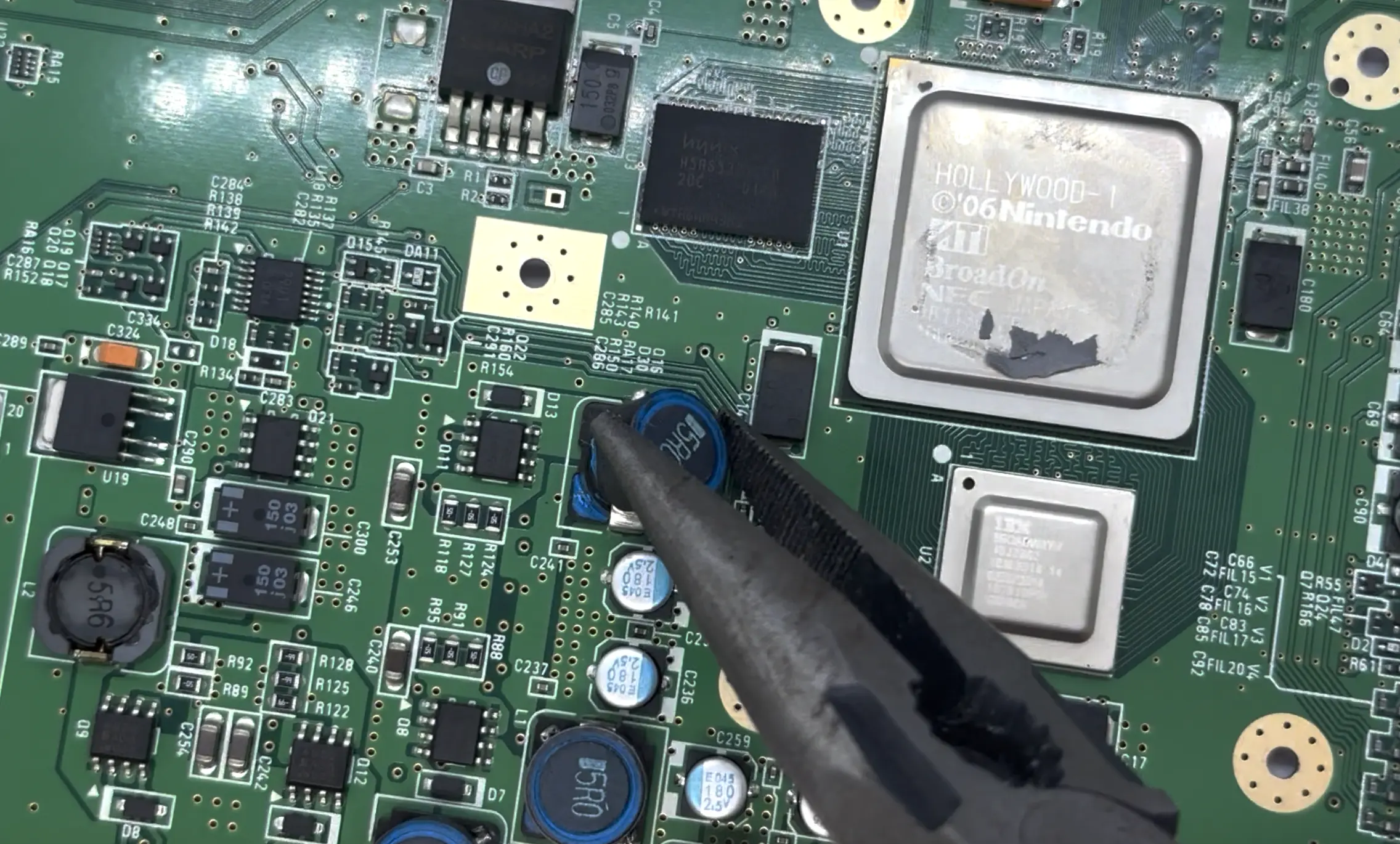
- Use a pair of pliers to remove the large electrolytic capacitors on the top side of the board. They are highlighted pink in the WII TRIM DIAGRAM - TOP. If any of these capacitor pads on the Wii rip, it is not a concern as they are not utilized by the Xii-Boy Ultra.
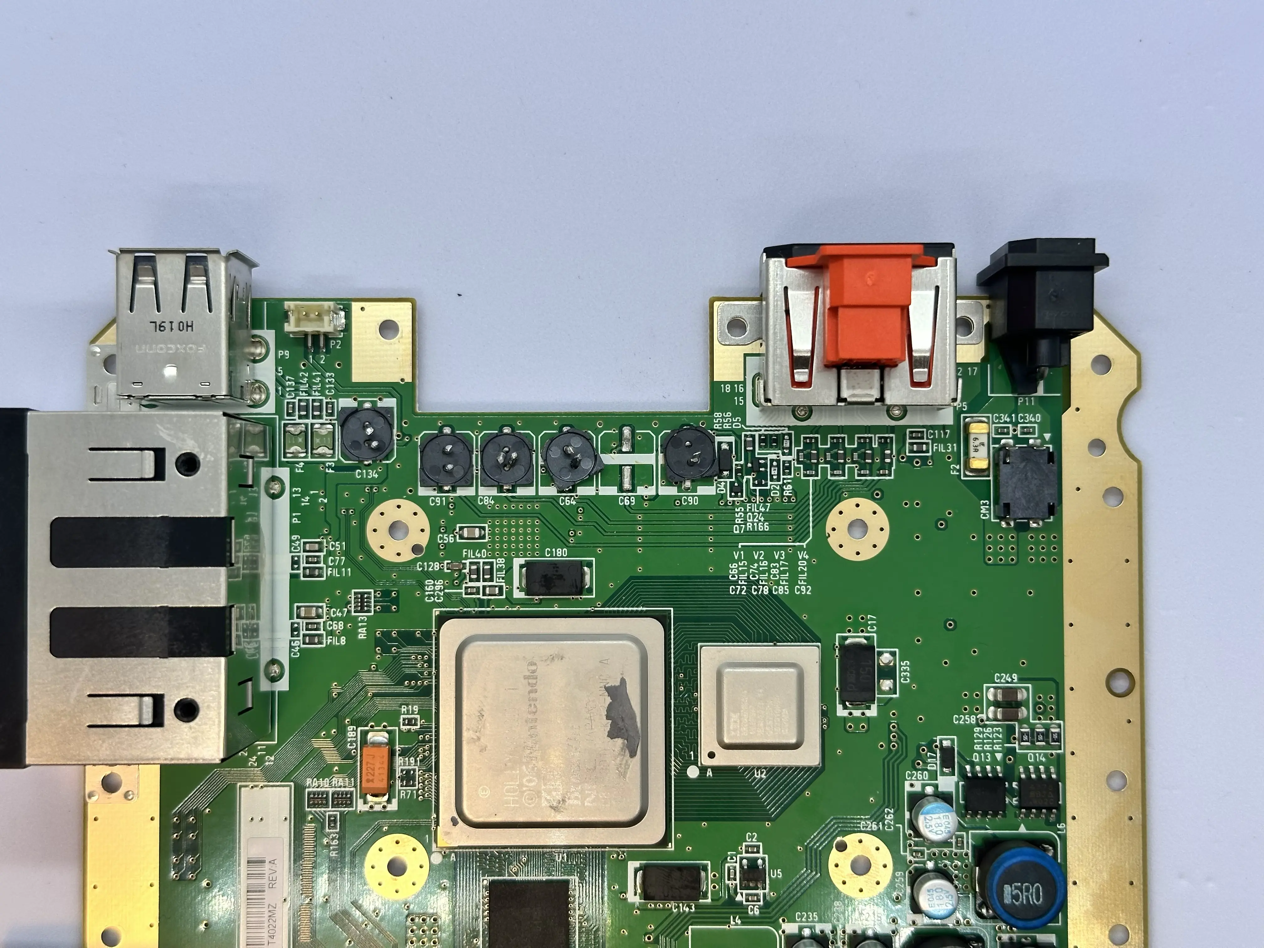
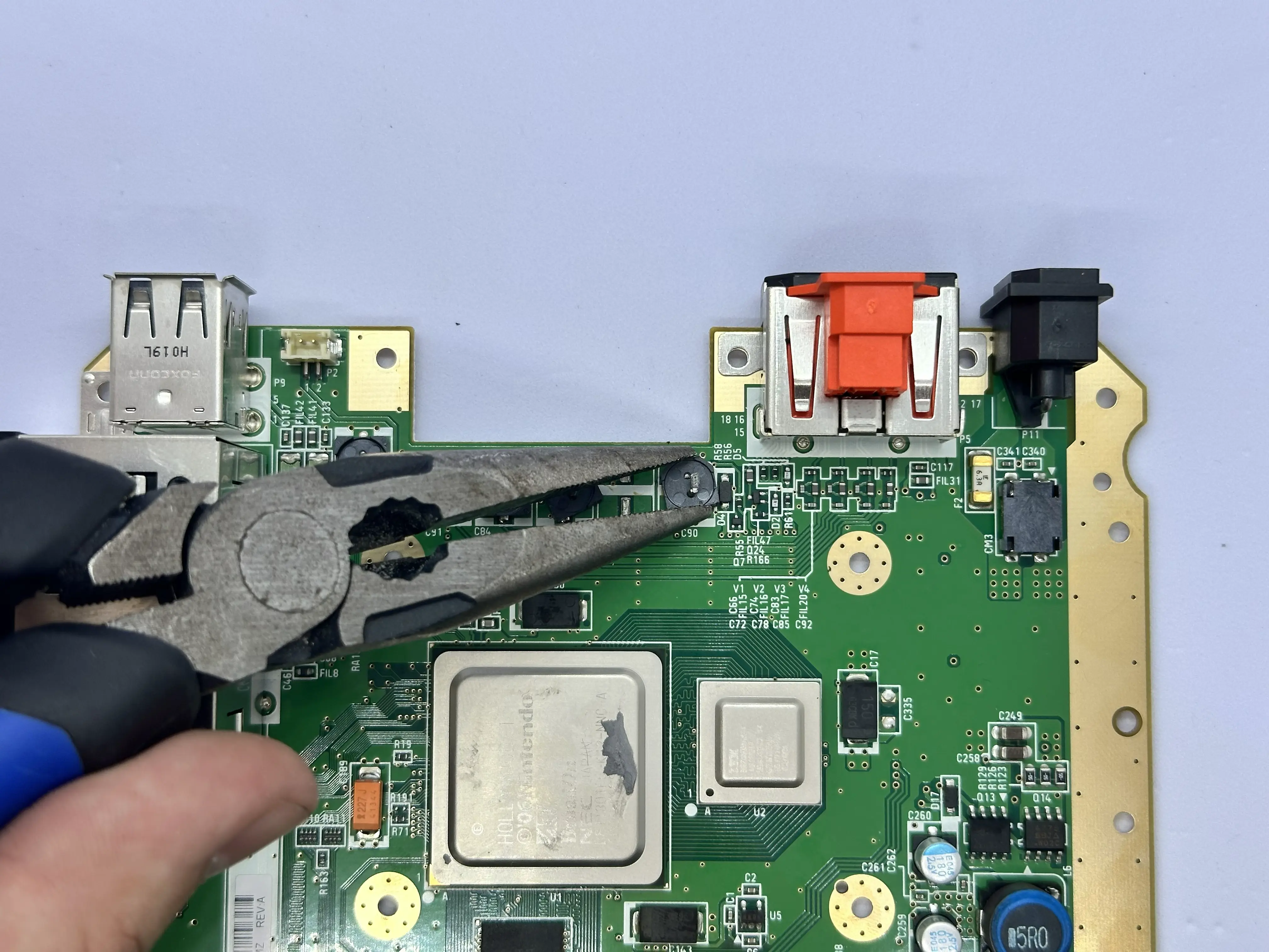
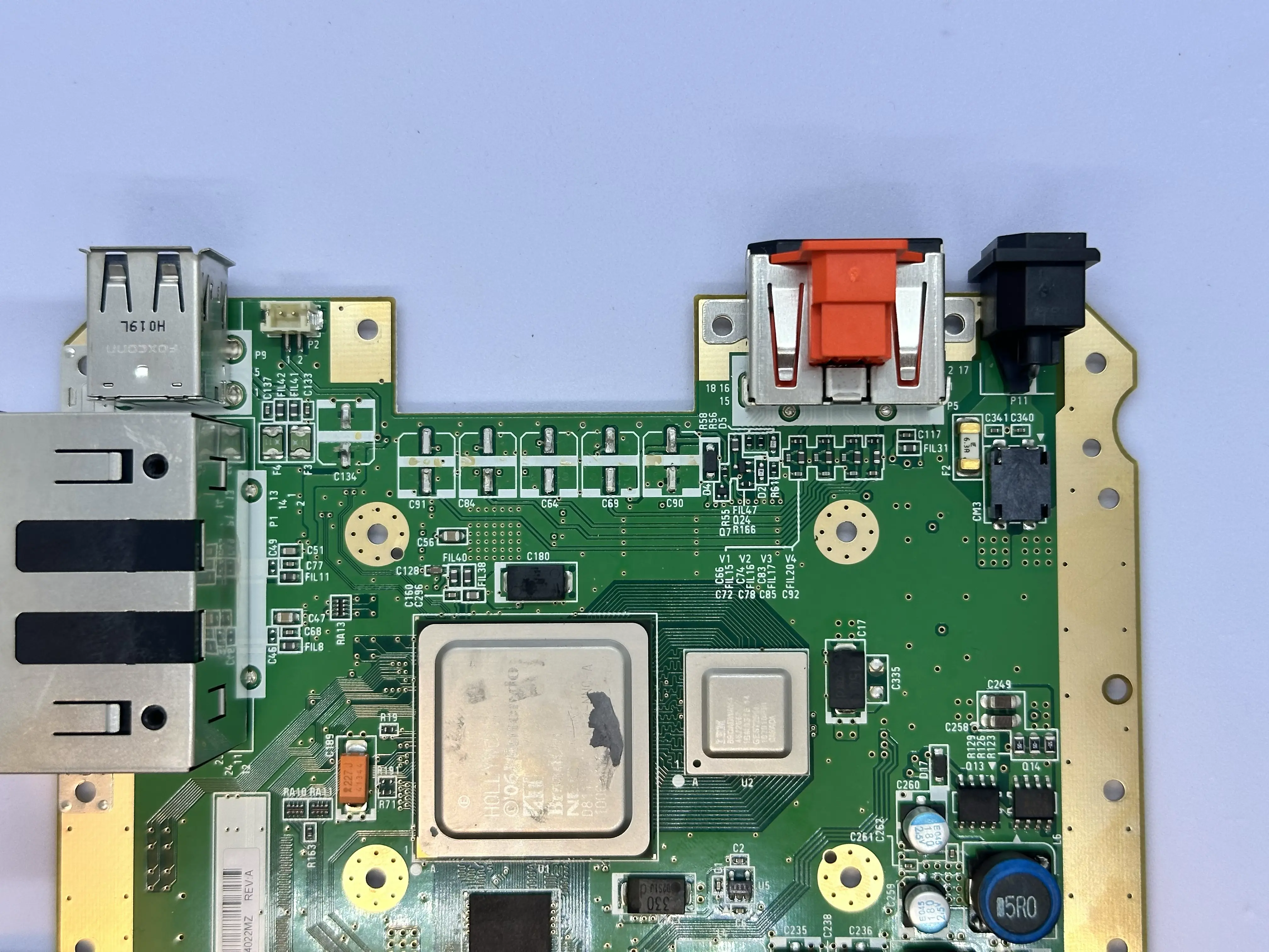
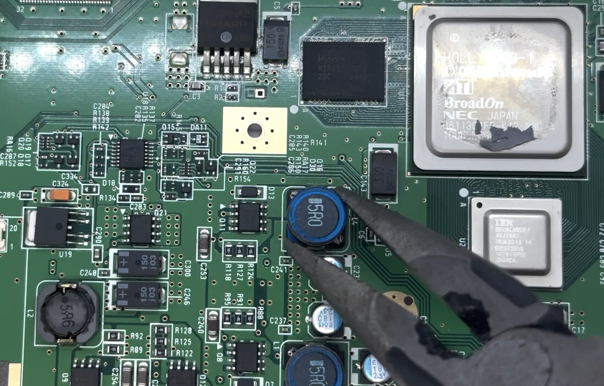
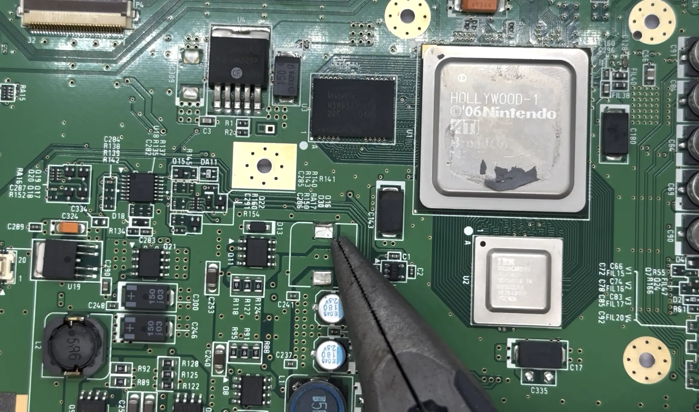
- Use a pair of pliers to remove the large inductor (
L4) located on the top side of the board, beneath the RAM. If this pad is ripped during the process, it is not a concern as the pad is not utilized by the Xii-Boy Ultra.
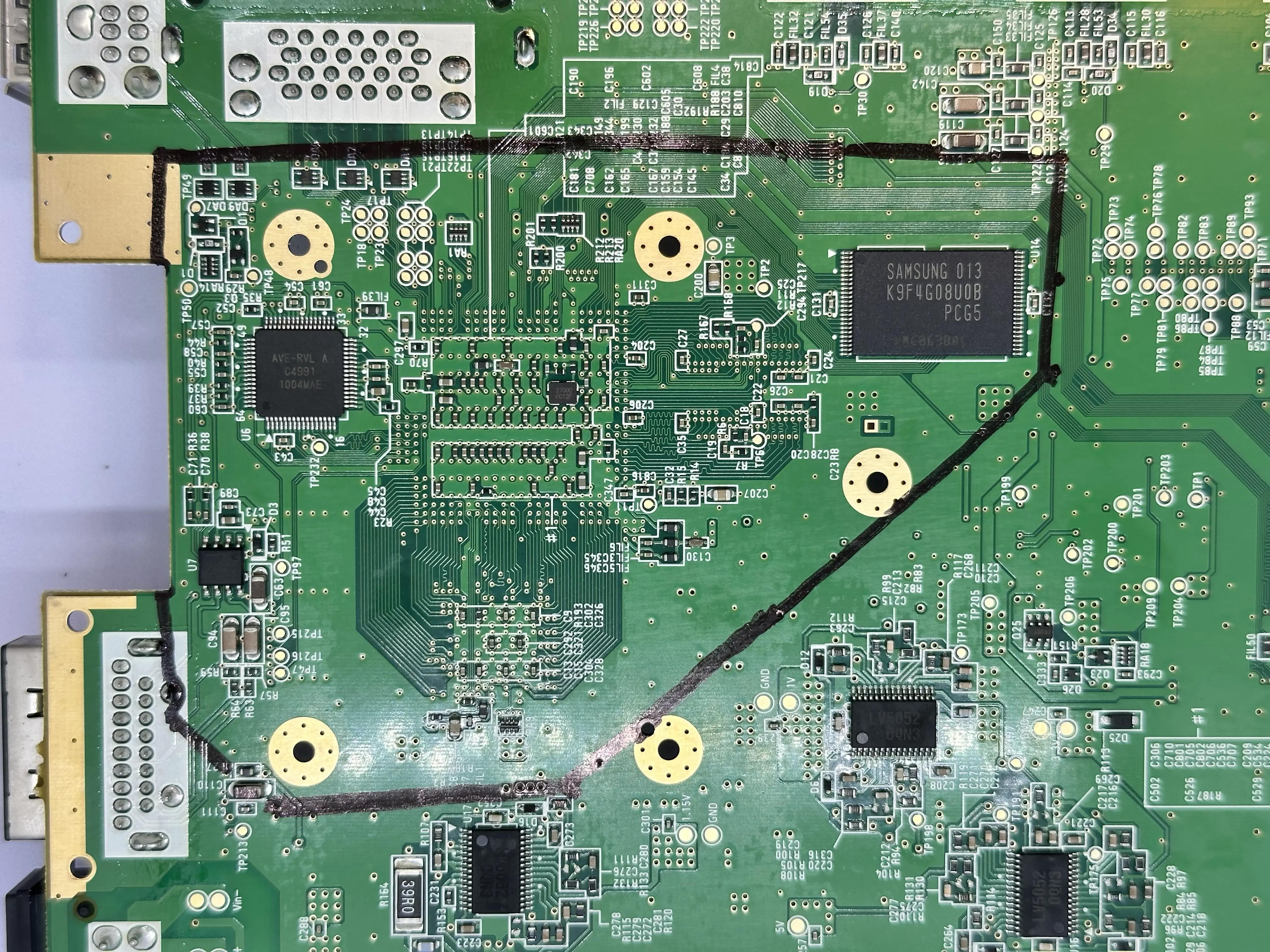
- Use a permanent marker and ruler to trace the trim outline on both the top and bottom of the board.
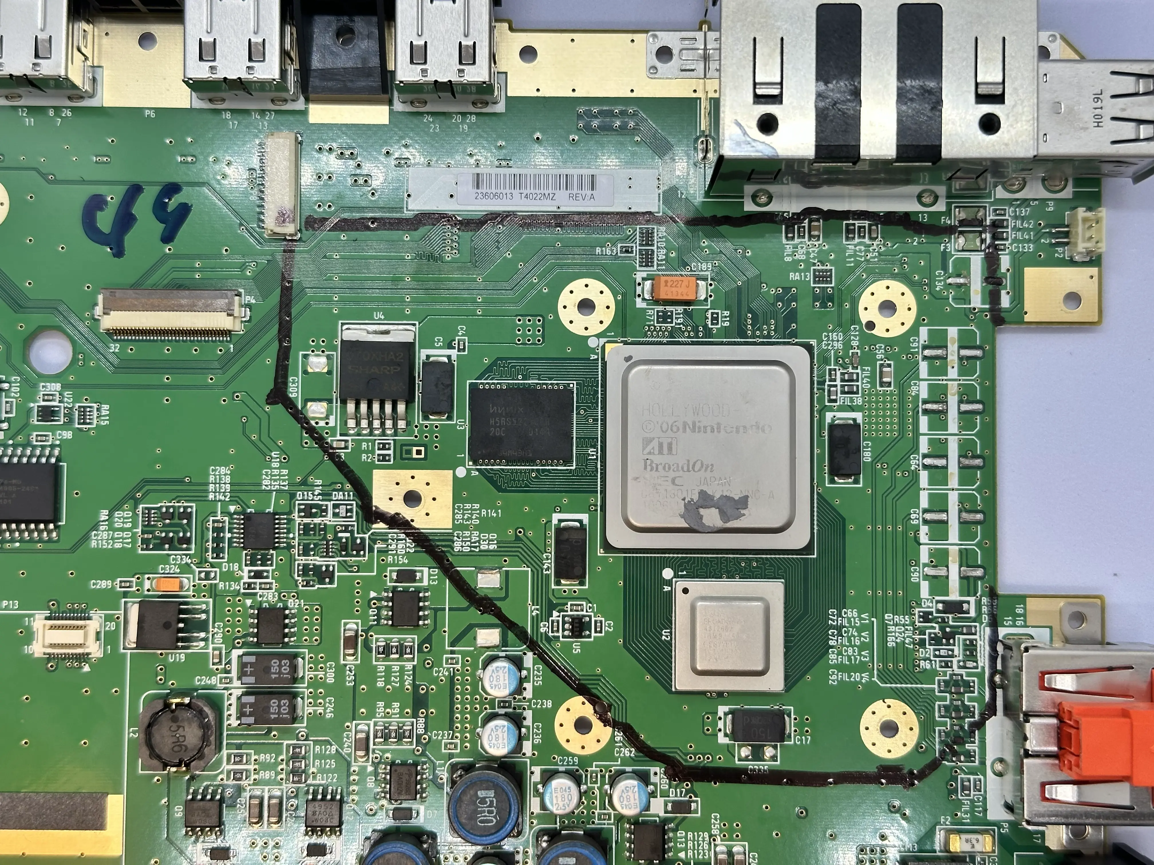
Apply masking tape over the GPU (Hollywood) and CPU (Broadway), keeping it flush with the board. This prevents copper shards from getting underneath the components while trimming.
Prepare for trimming: Attach the diamond cutting wheel to the Dremel and fasten it tightly. Move to a well-ventilated area and put on a mask, safety glasses, and gloves. A respirator rated for fine particulate matter (P100 or N95 minimum) is required.
Important
Cutting PCBs releases dust and shards. These micro-plastic dust clouds and copper shards can cause permanent lung damage. Equip proper safety gear to protect your eyes and lungs.
- Begin trimming slowly against the rotation of the wheel, cutting slightly outside the trim line as the Wii will need to be sanded afterwards. If a component on one side blocks the Dremel, switch sides. Be extremely cautious of Critical Passives (Red) and Core ICs (White) in the diagram.
Note
Do NOT apply force with the Dremel. The wheel does the cutting; you are only guiding it. Force can cause it to skip and hit critical components.
- Once trimming is complete, sand the edges with progressively finer grits of sandpaper:
180 → 200 → 300 → 400 → 600 → 800 → 1000 grit (anything higher than 1000 grit is optional). Low grits remove more of the board; high grits remove small amounts and create a smooth finish. Sand away burs or extrusions. At 1000 grit, each of the four layers should be distinct and the sides smooth.
- Remove tape and clean the board. Trimming is finished!
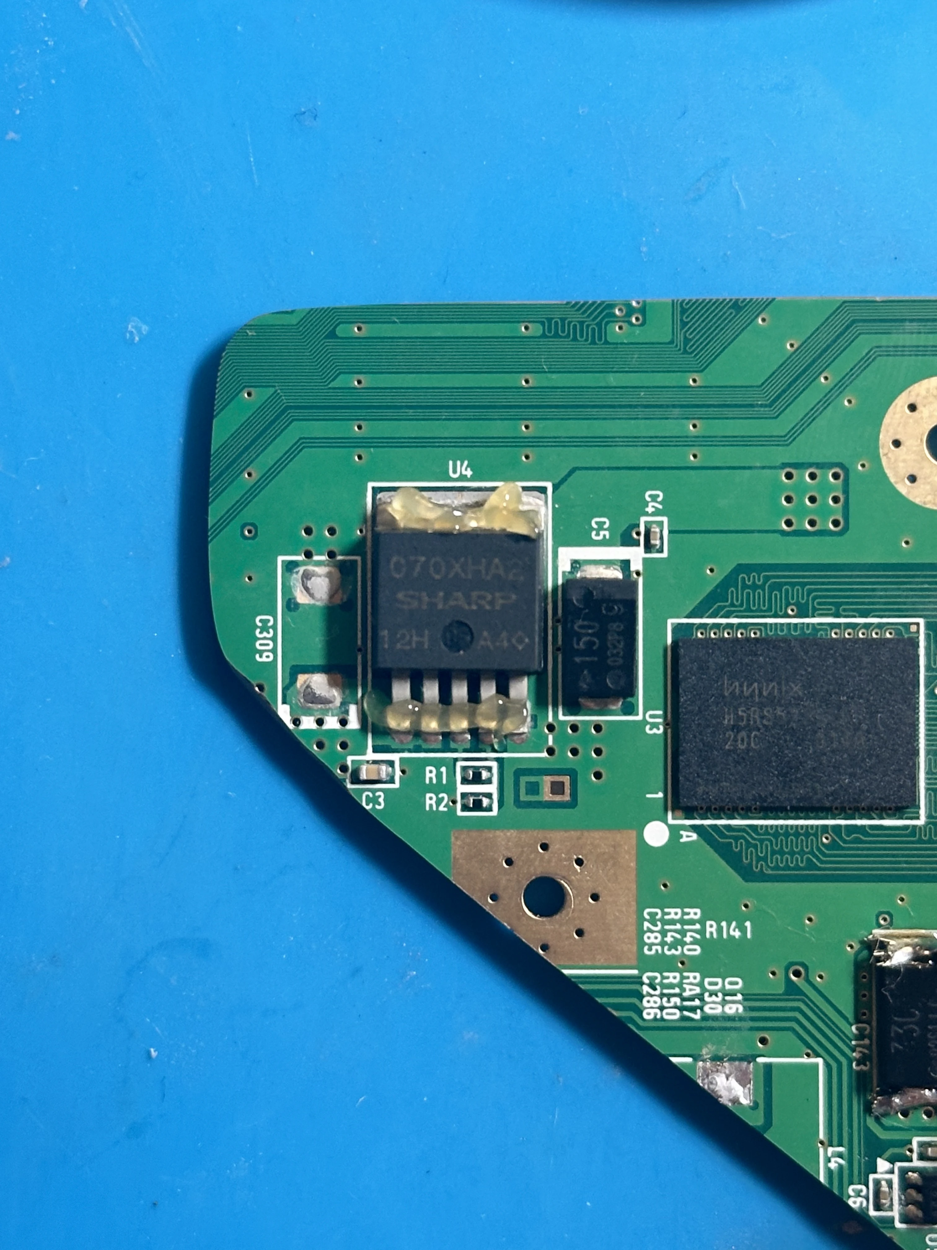
1.8V LDO Removal
The trimmed Wii motherboard contains a 1.8v LDO (Voltage regulator) which needs to be removed to work with the RVL-PMS2.
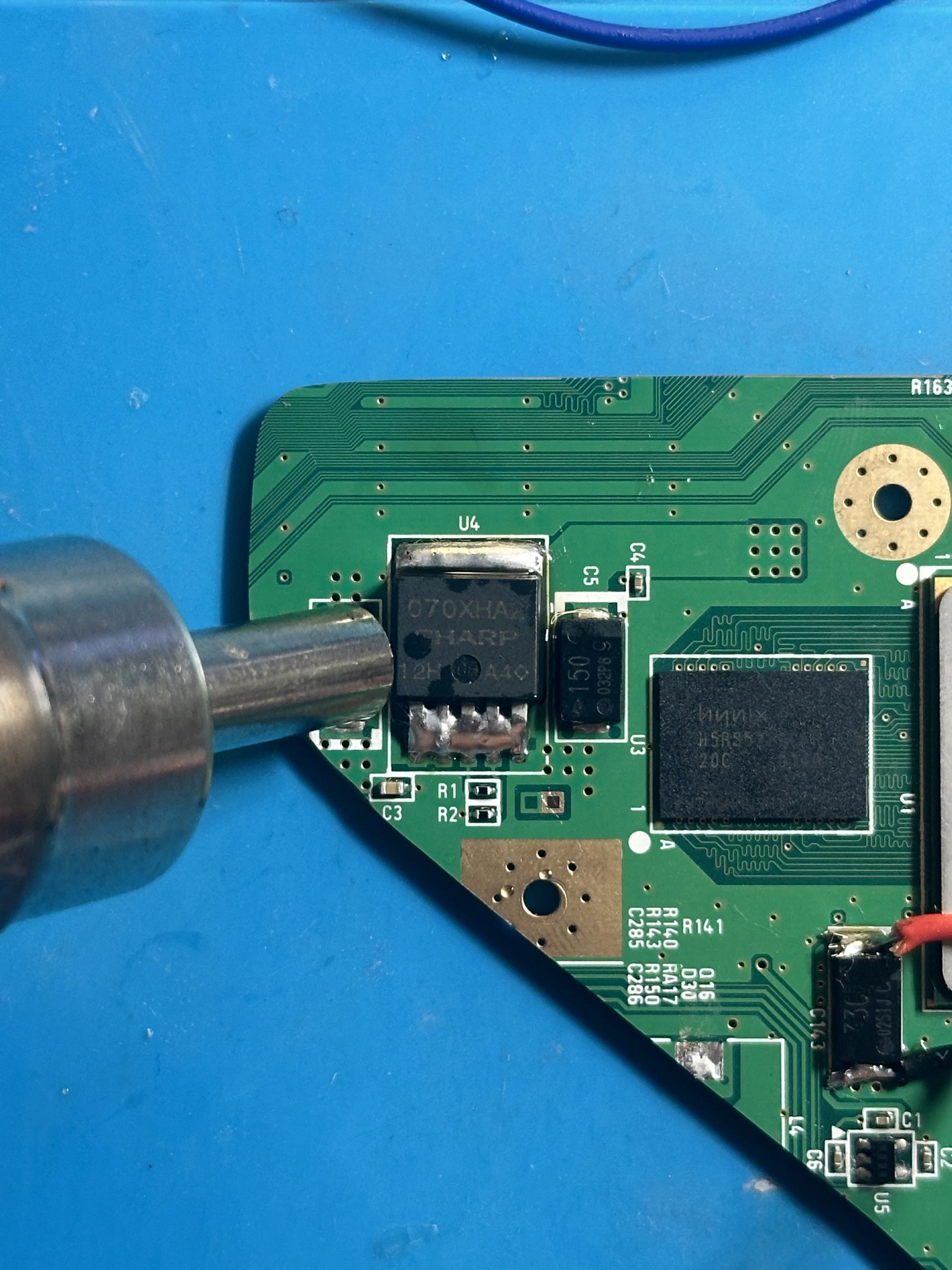
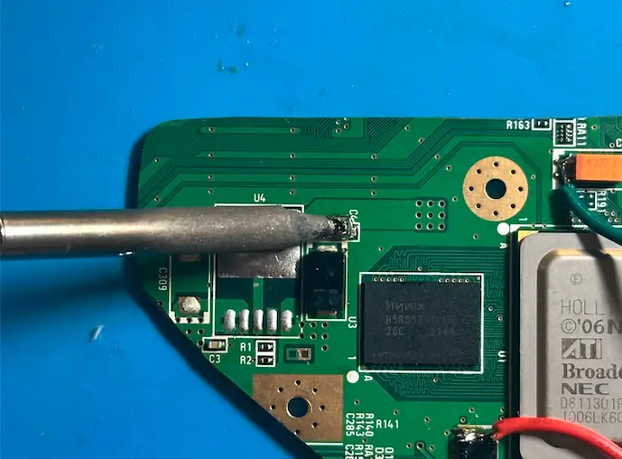
- On the top of the trimmed Wii, locate the
1.8v LDO(Designated asU4on the silkscreen) and apply flux to the top pad and bottom 5 pins. - Use a soldering iron and flood the pad and pins with excess solder. The pins are okay to connect to each other here since no power is being applied.
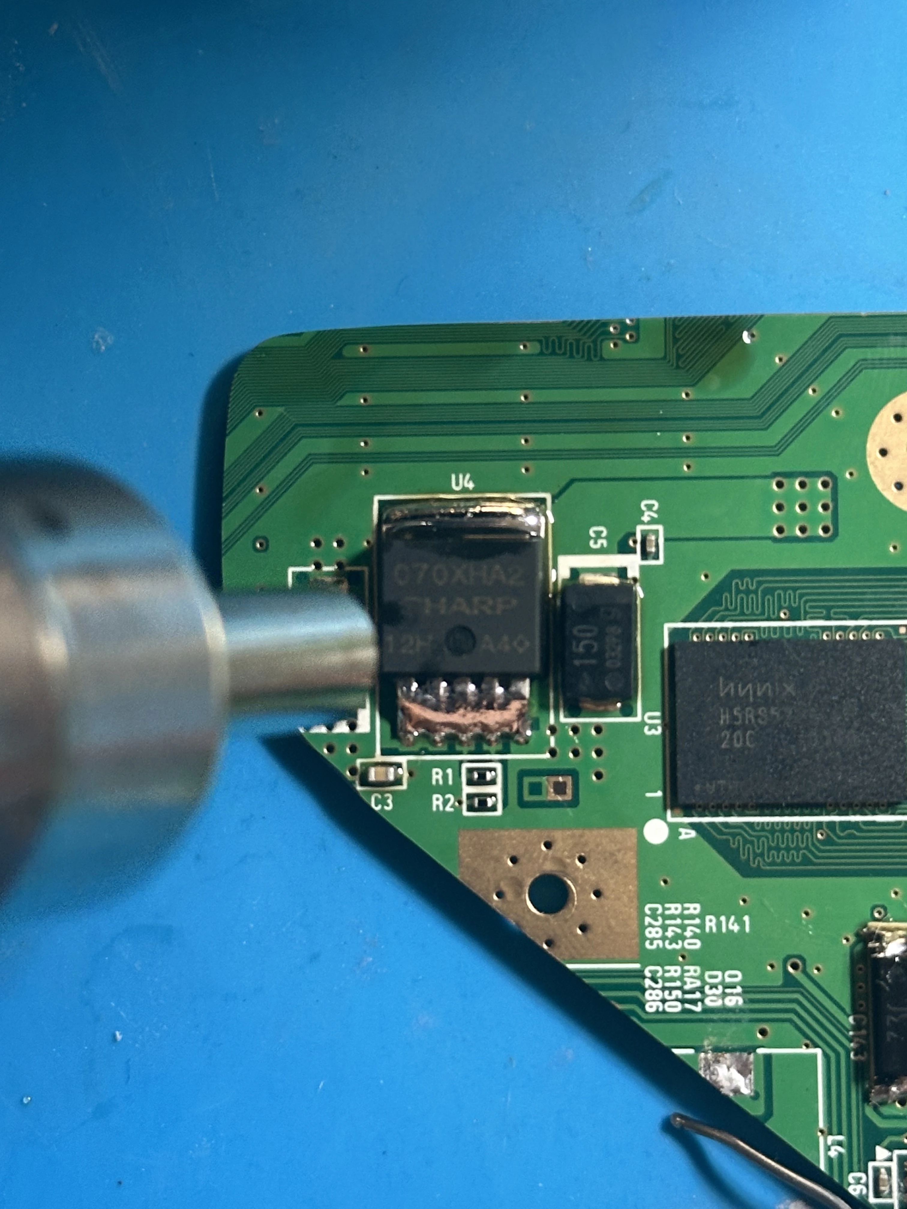
- Set a hot air gun/station to
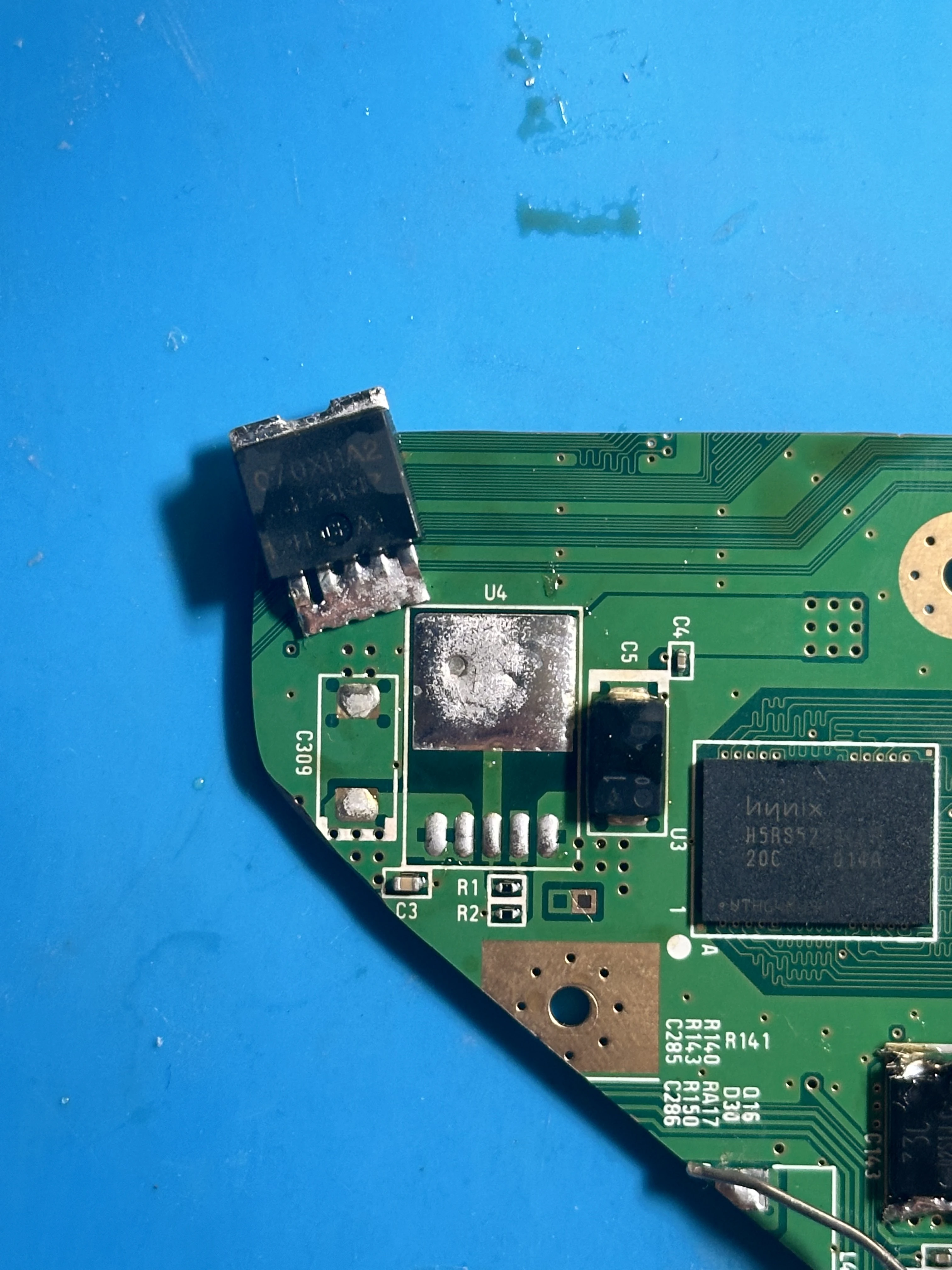
425°C at 80% airflowand use a medium or large nozzle. Aim the nozzle at the1.8v LDOand keep it only a few cm away. Move the hot air gun around in a circular motion over the part, and continue until all the solder is molten. - Use a pair of tweezers to slide the
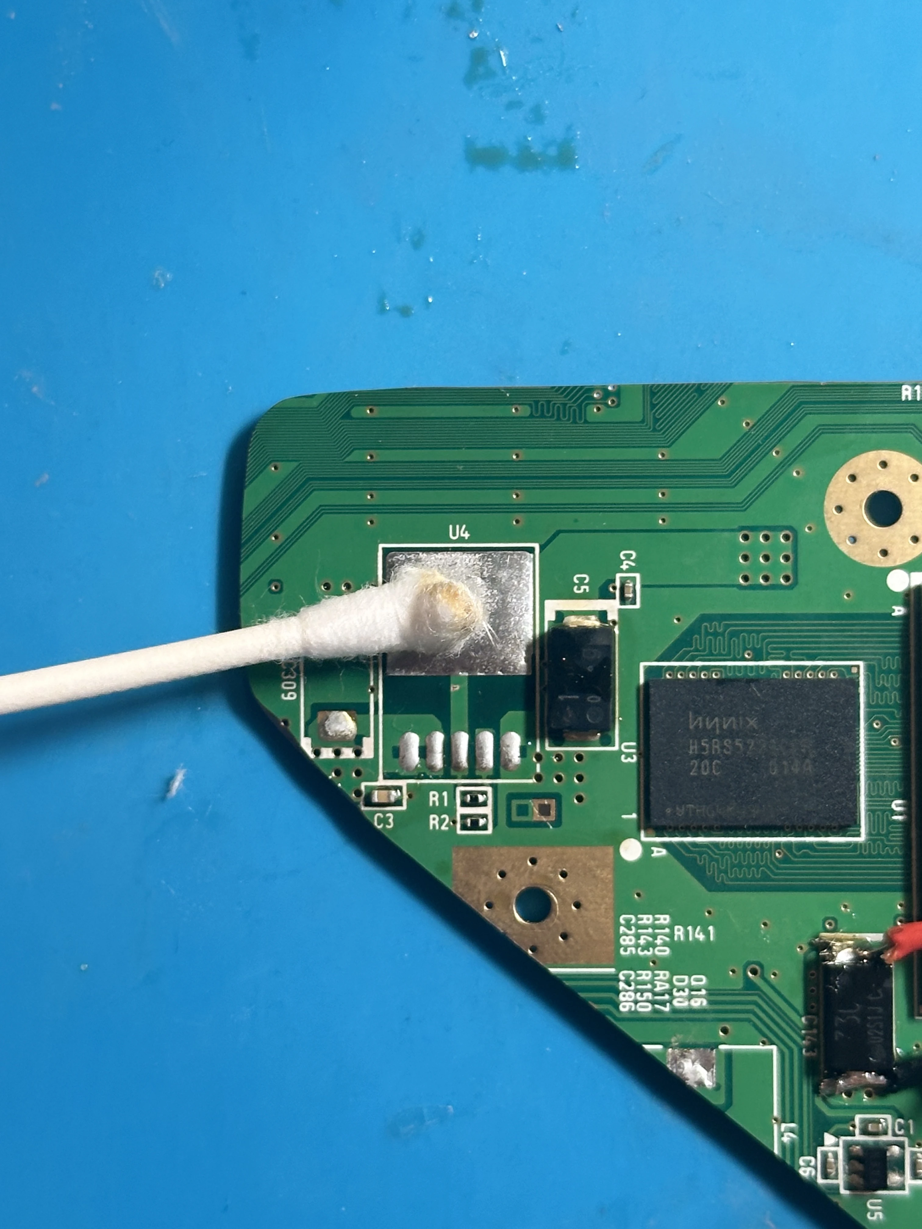
1.8v LDOoff the board. Do not apply excessive force, as the solder may not be completely molten and traces would rip. - Dispose of the
1.8v LDOand clean the area using a Q-tip and 91% isopropyl alcohol.
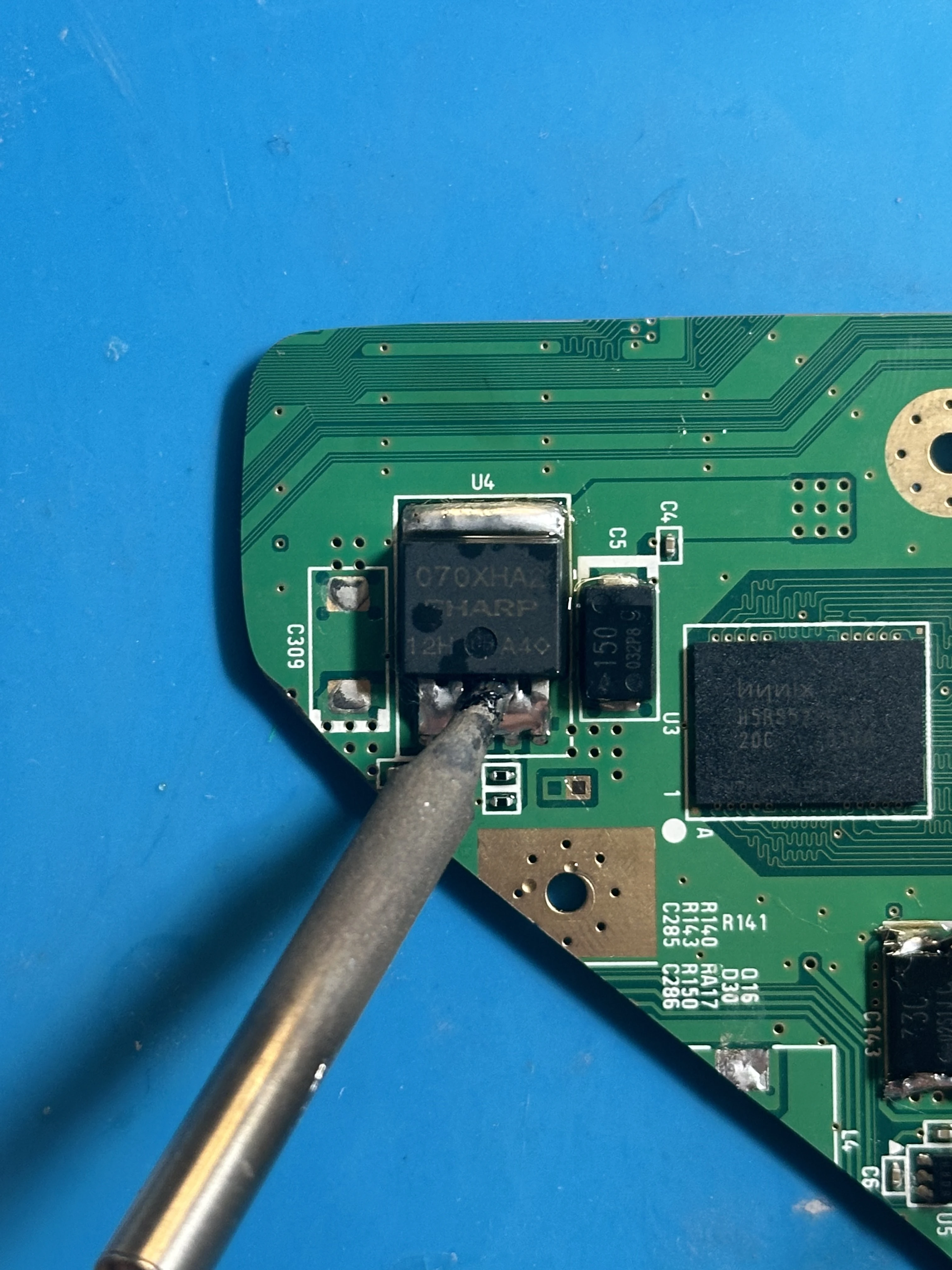
Using a Soldering Iron Instead of a Hot Air Gun
It is also possible to remove the 1.8v LDO using a soldering iron and dremel instead of a hot air gun. To do this, cut the 5 pins on the bottom of the LDO using the dremel without cutting into the PCB. Then, heat each pin with a soldering iron and remove them one-by-one. After the pins are removed, set the soldering iron to a high temperature (425°C) and let it heat the top LDO pad until the LDO is able to slide off.
C4 Capacitor Removal
Capacitor C4 next to the 1.8v LDO needs to be removed in order for the Xii-Strip to sit flush against the board.
- Push a large soldering iron tip against the side of the capacitor and stay there until the capacitor heats up.
- The capacitor is small, so this should only take a few seconds. After it is loose, push it off the board and dispose of it.
- Clean the area using a Q-tip and 91% isopropyl alcohol.
Testing a Trimmed Board
Perform essential tests before powering the trimmed Wii to ensure functionality. Confirming functionality now saves troubleshooting headaches later.
Wii Resistance Checker
Important: Before measuring, ensure the multimeter is set to the 20kΩ resistance mode. Additionally, verify that no external components are connected to the motherboard.
Once the resistances are correct and the board passes testing, proceed to the next section:
- Connect the RVL-PMS2 to the Wii. Solder a wire from each voltage pad on the RVL-PMS2 to the respective pad on the Wii (e.g., 3.3v → 3.3v). Use 24 AWG wire and keep wires short.
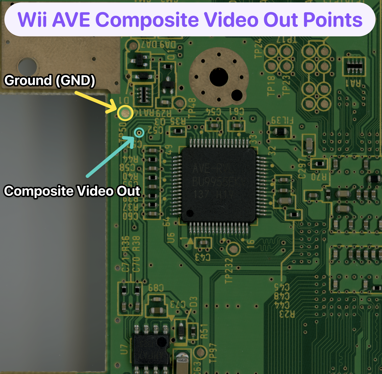
- Connect outlined AVE pads on the Wii to a stripped RCA cable. The original Wii composite cable and a trimmed video connector can work in a pinch. Connect the cable to a composite-compatible display.
- Connect a battery to the 'B+' and 'B-' pads on the RVL-PMS2. Short the 'BTN' pad with 'GND' for three seconds using a button or tweezers to activate the RVL-PMS2 and output all voltage rails.
- The Wii will display an error on screen (good error, confirming trim and RVL-PMS2 are working).
- Desolder all wires from both the Wii and RVL-PMS2.