Top Half Assembly
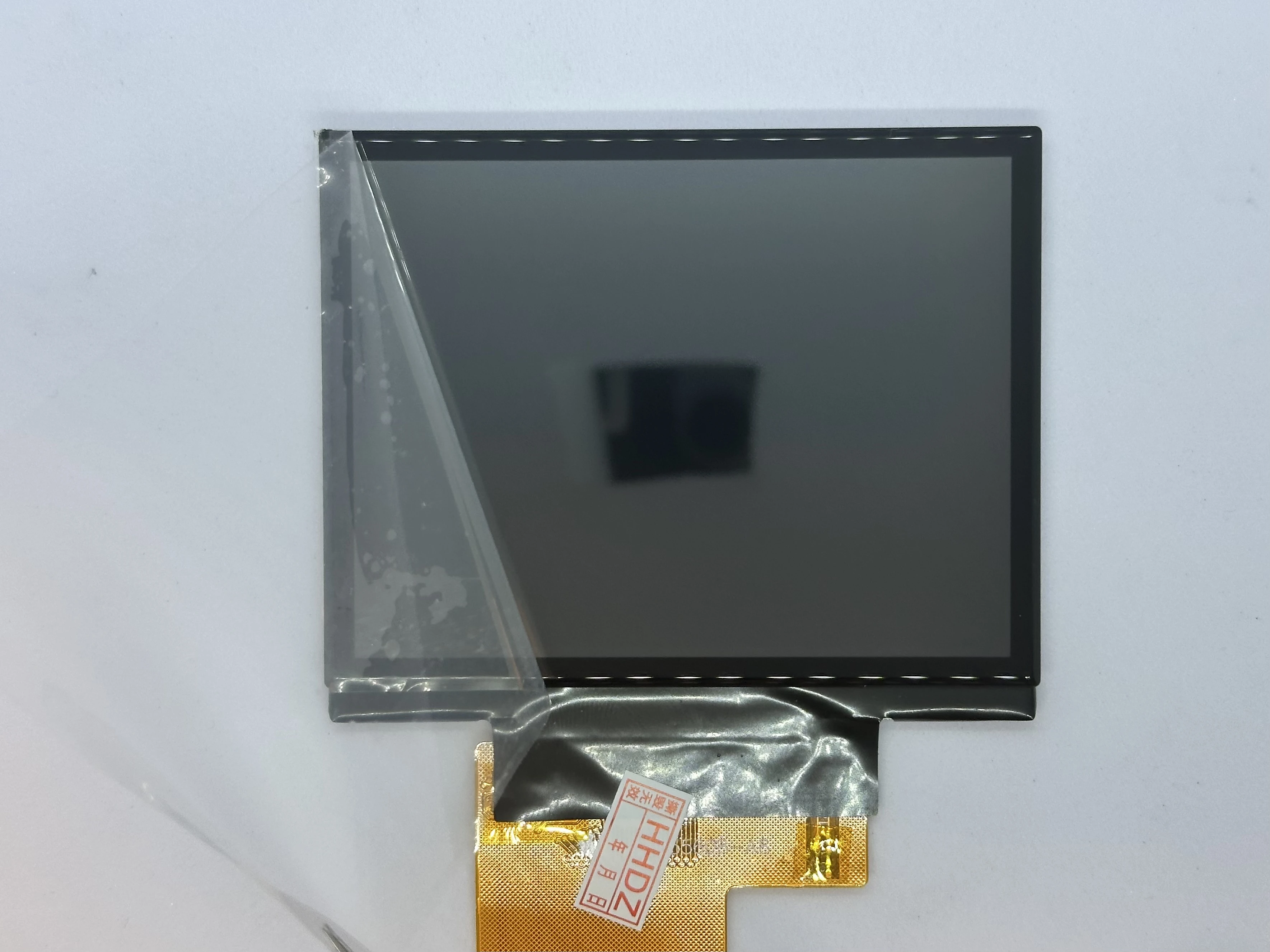
Installing the Display
- Retrieve the display from Bag T1. Peel off the film covering the front of the glass.

- Retrieve the front shell from Bag G1. Place the display into the top shell at a 45° angle. The bottom of the display should sit flat on the indent of the case, and the ribbon cable should go through to the inside.
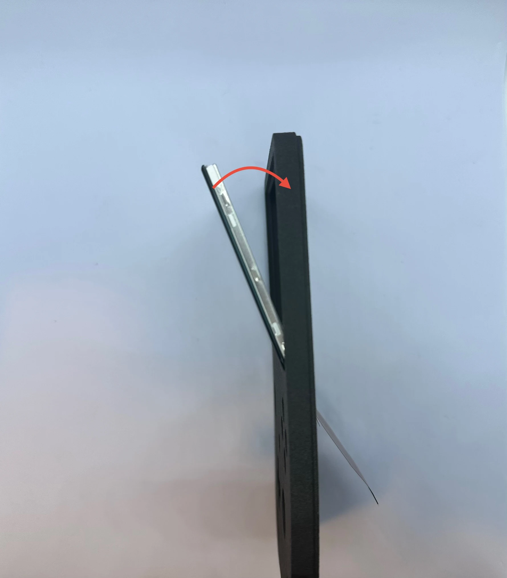
- Slowly rotate the screen toward the front of the shell. At the very end, a small amount of force may be required to set the display in place. A small lip surrounds the indent, and a soft “click” will indicate the display is snapped into place.
NOTICE
After the click, the display will be held in by friction and the lip. It is not recommended to remove the display more than once or twice, as this can cause issues with the fitting.
Xii-DD PCB (XBU-002)
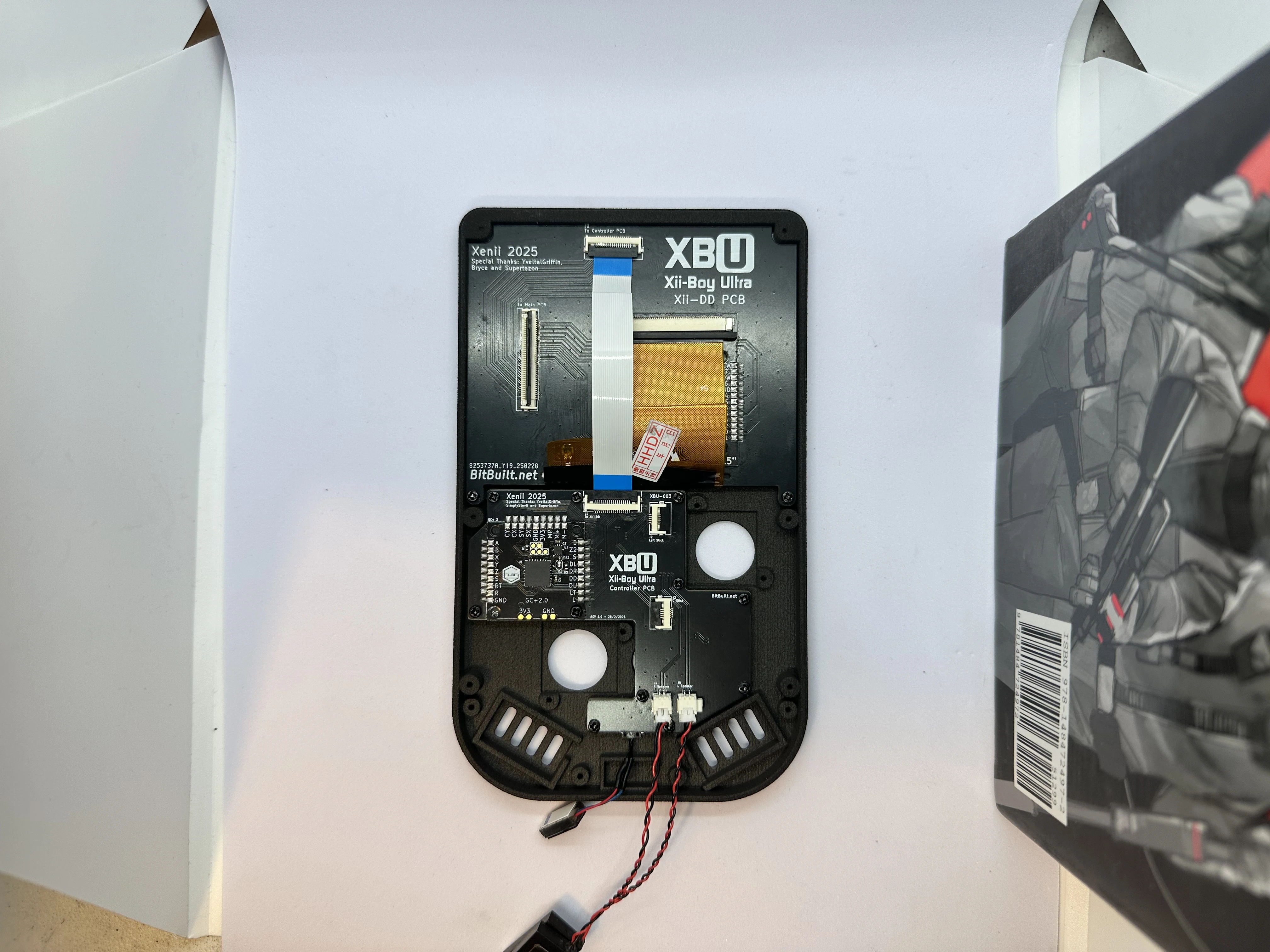
- Flip the top shell so the external side is facing down. Retrieve the Xii-DD PCB from Bag T2. Then, slide the Xii-DD PCB at a
20°angle on the back of the display until it pushes against the top of the shell and underneath the notch. Fasten the Xii-DD PCB in place using two4mmPhillips screws from Bag G3.
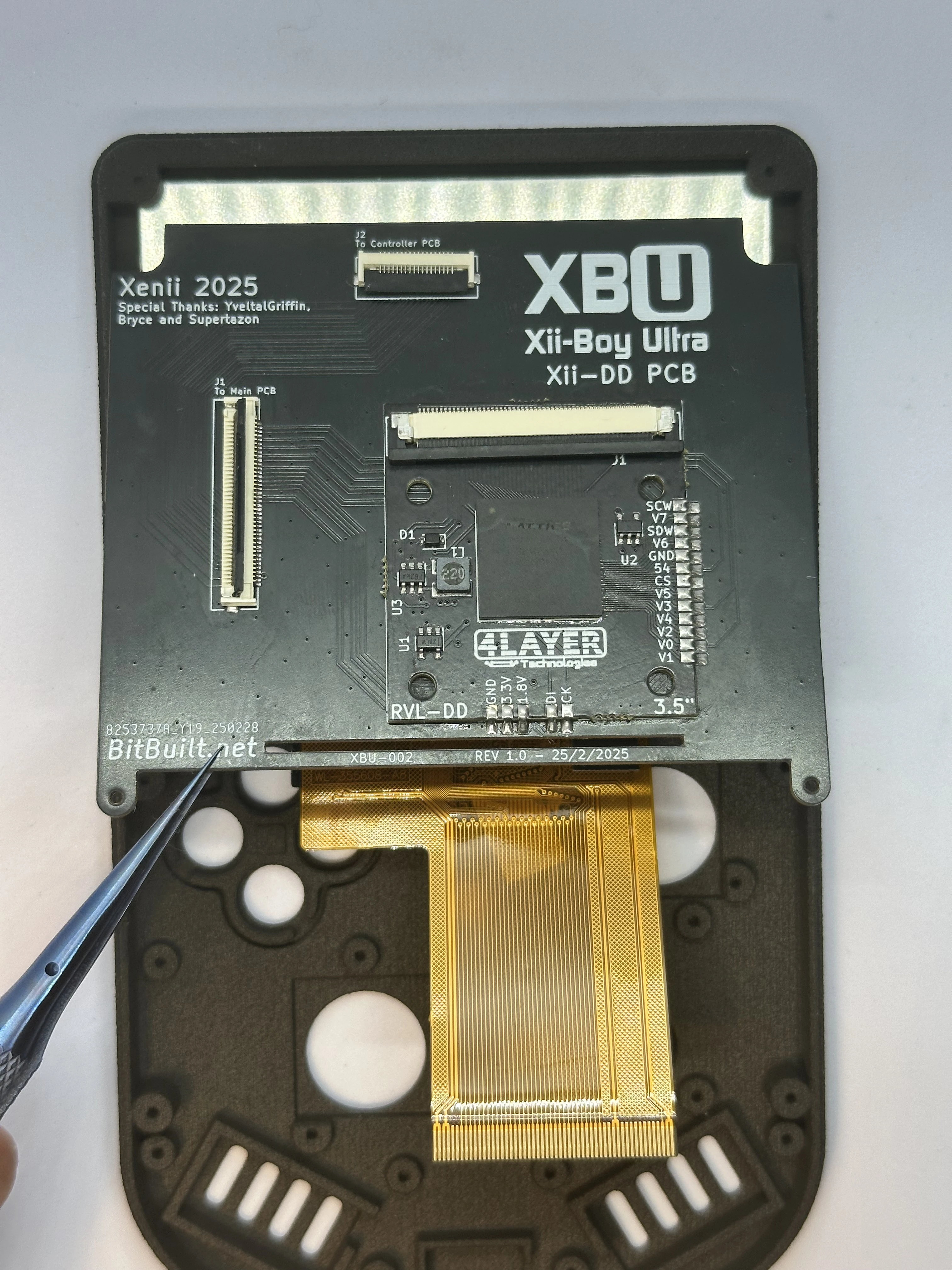
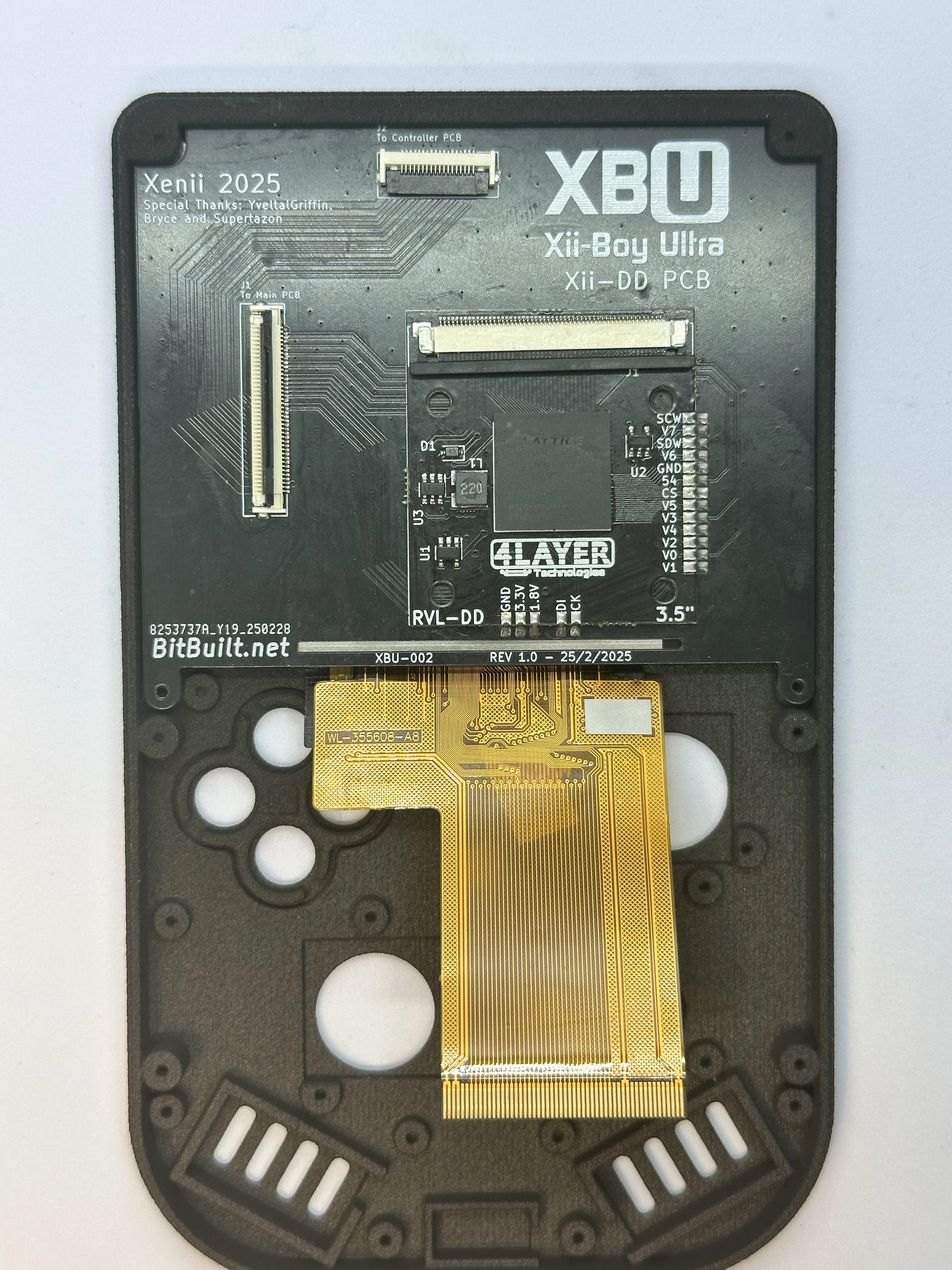
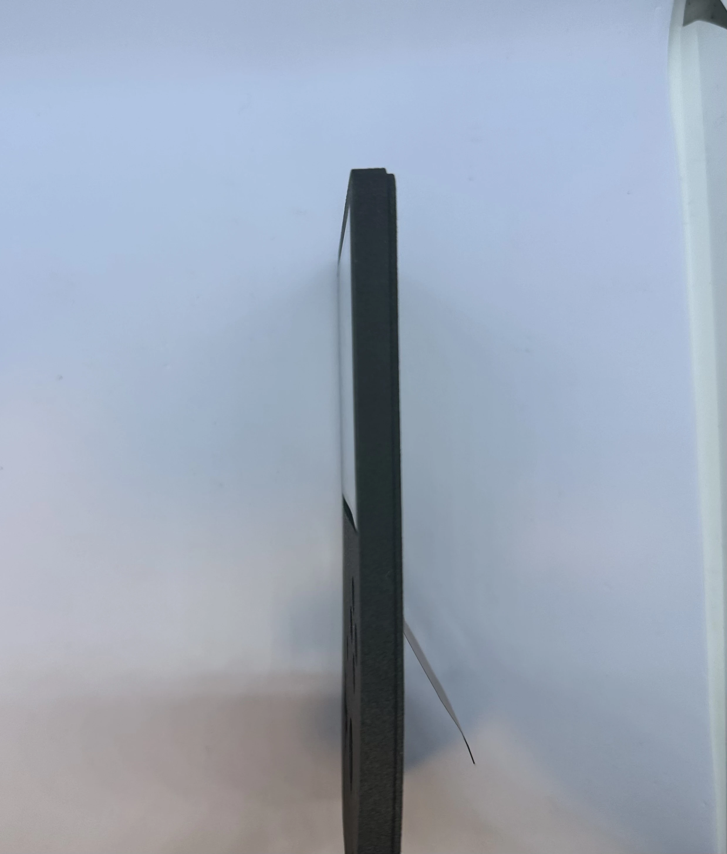
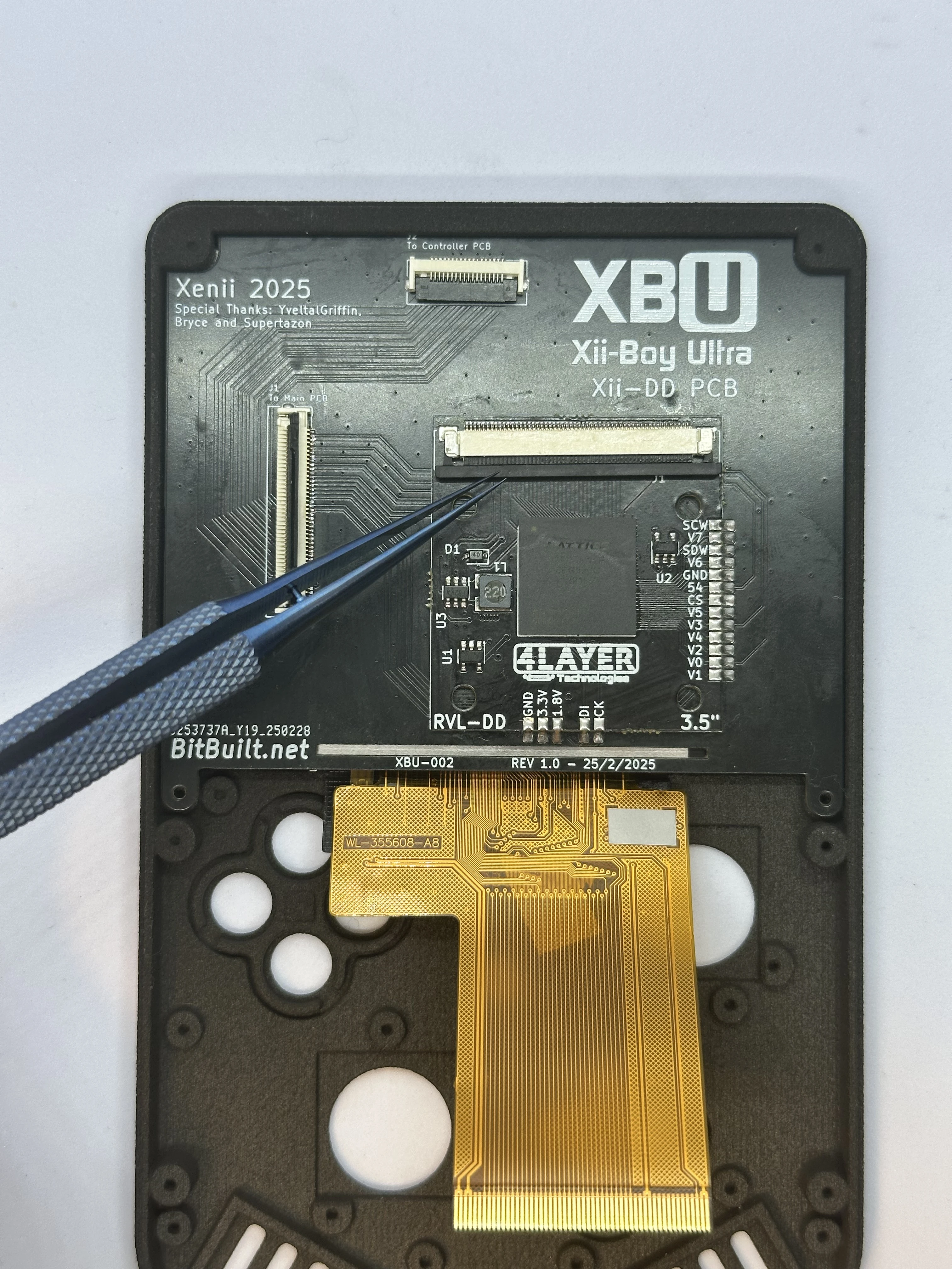
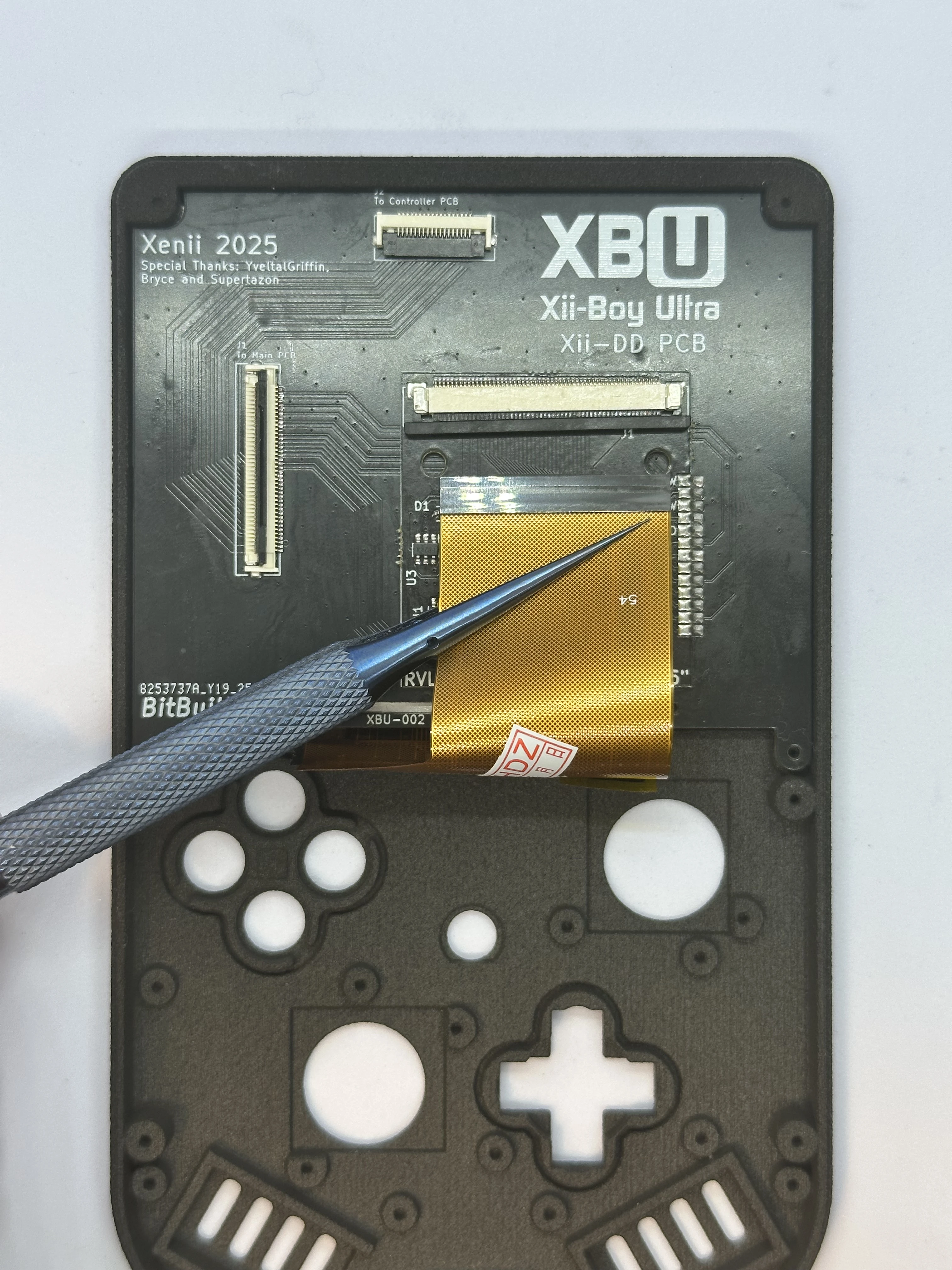
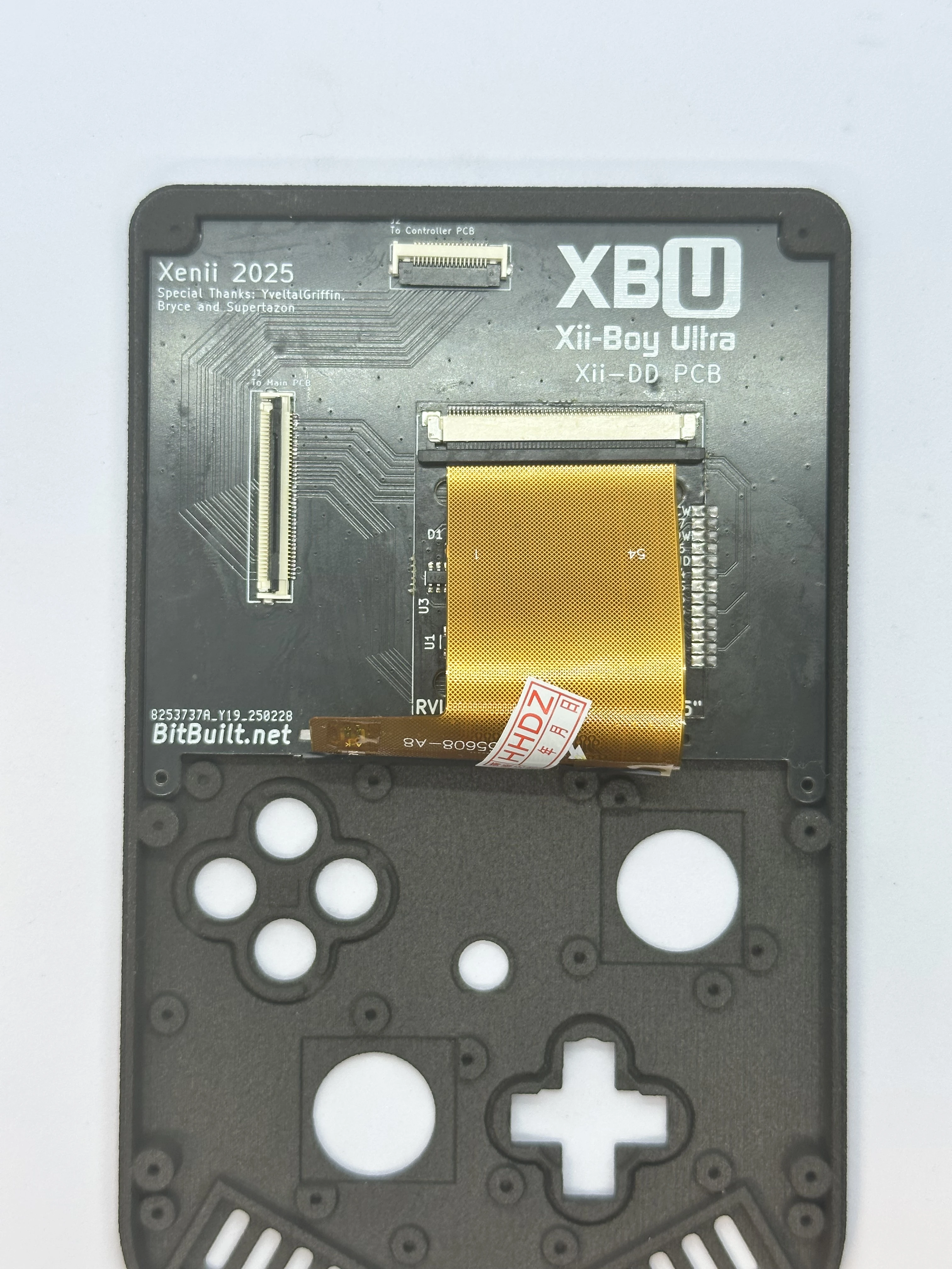
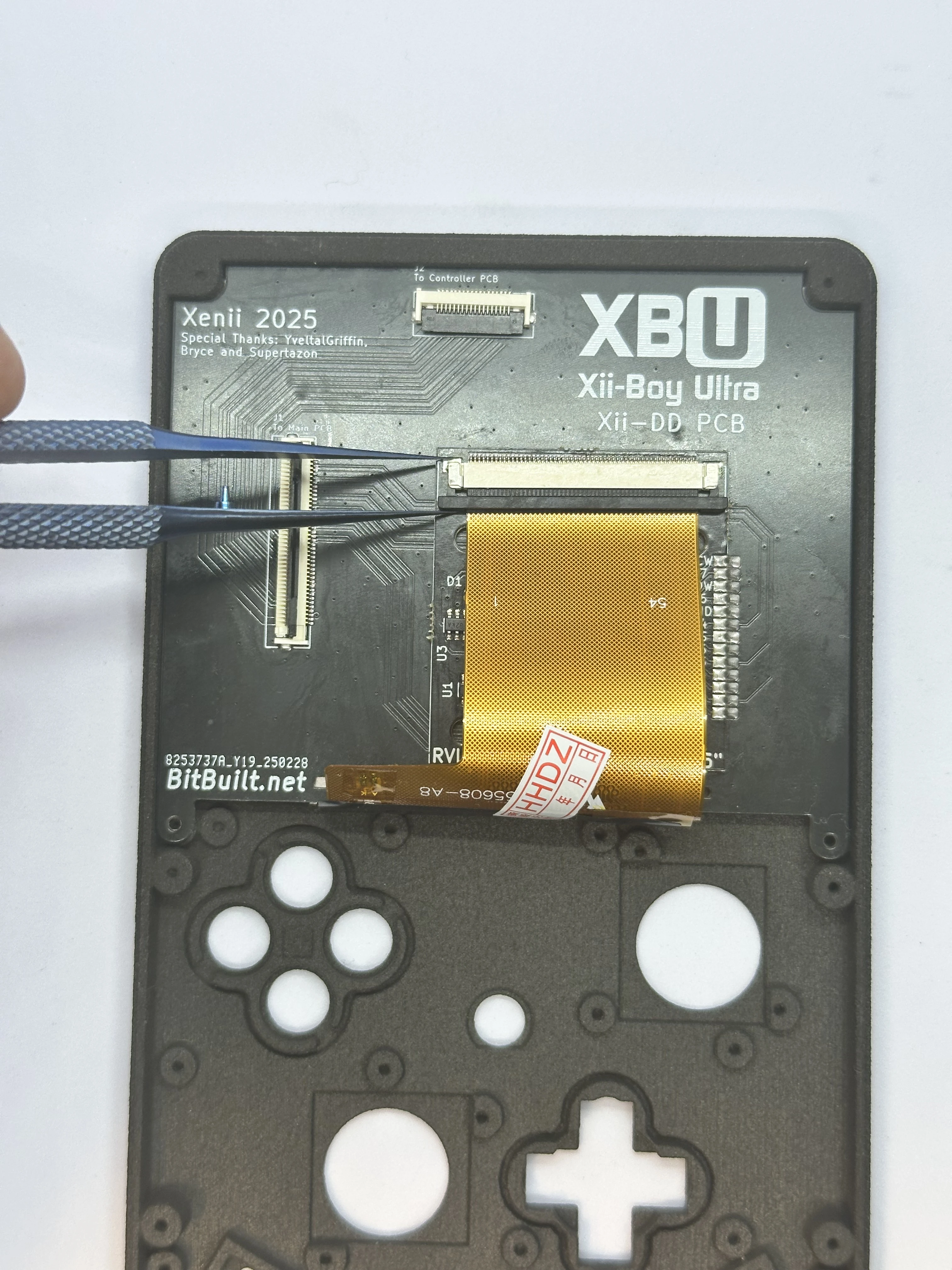
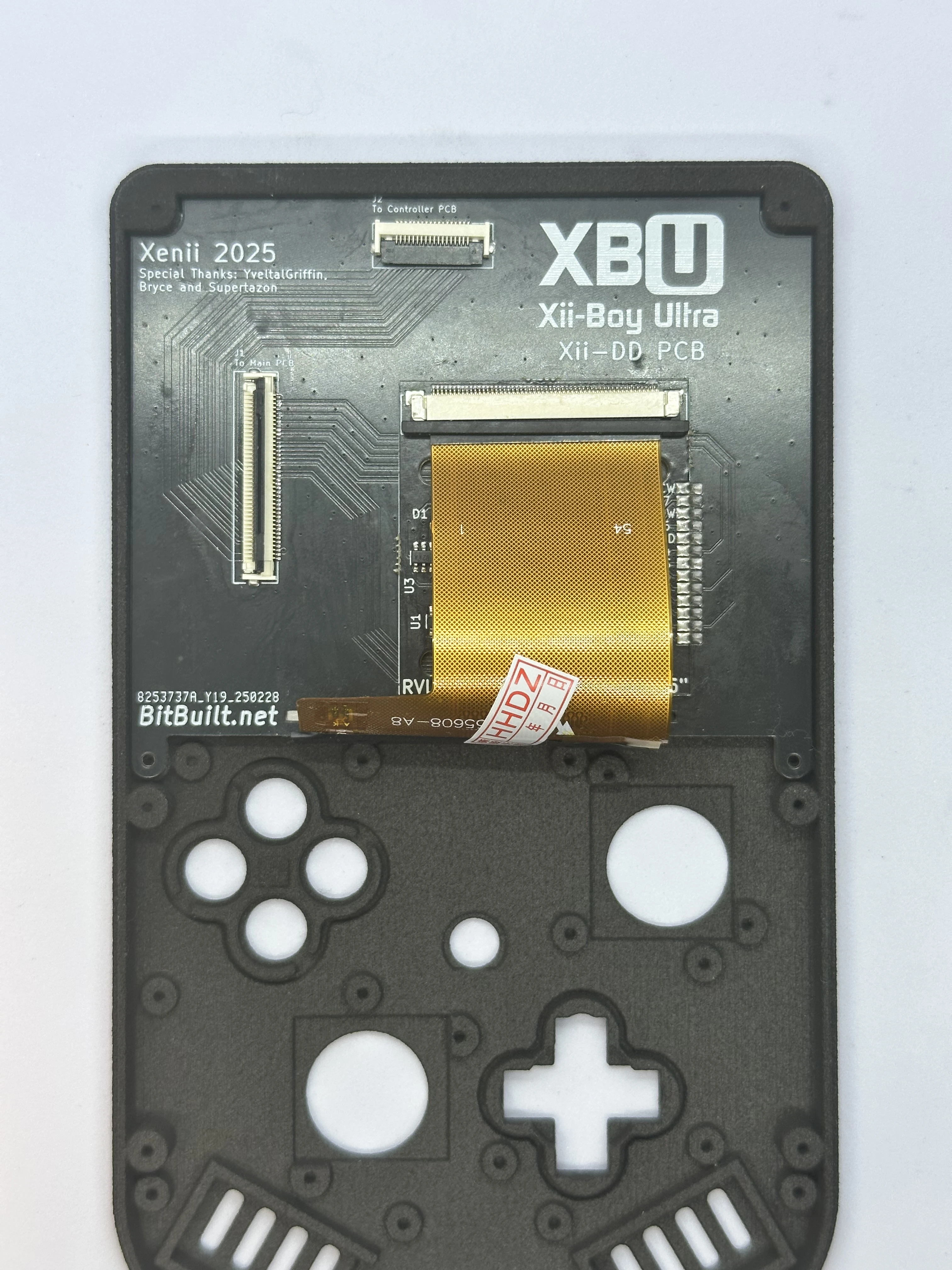
Open the slider ZIF connector on the RVL-DD. This ZIF is different from all others used in the XBU. To unlock it, pull directly away from the connector on both sides using a small amount of force. Do NOT pull up on it at all. The connector is fully unlocked when it extends out
1-2mmand is even across both sides.Fold the 3.5" display’s cable over the bottom edge of the Xii-DD PCB. Align it properly and carefully push the cable into the unlocked ZIF connector. Ensure it is pushed in all the way, as it can get stuck easily. Then, lock the ZIF connector.
Face Buttons
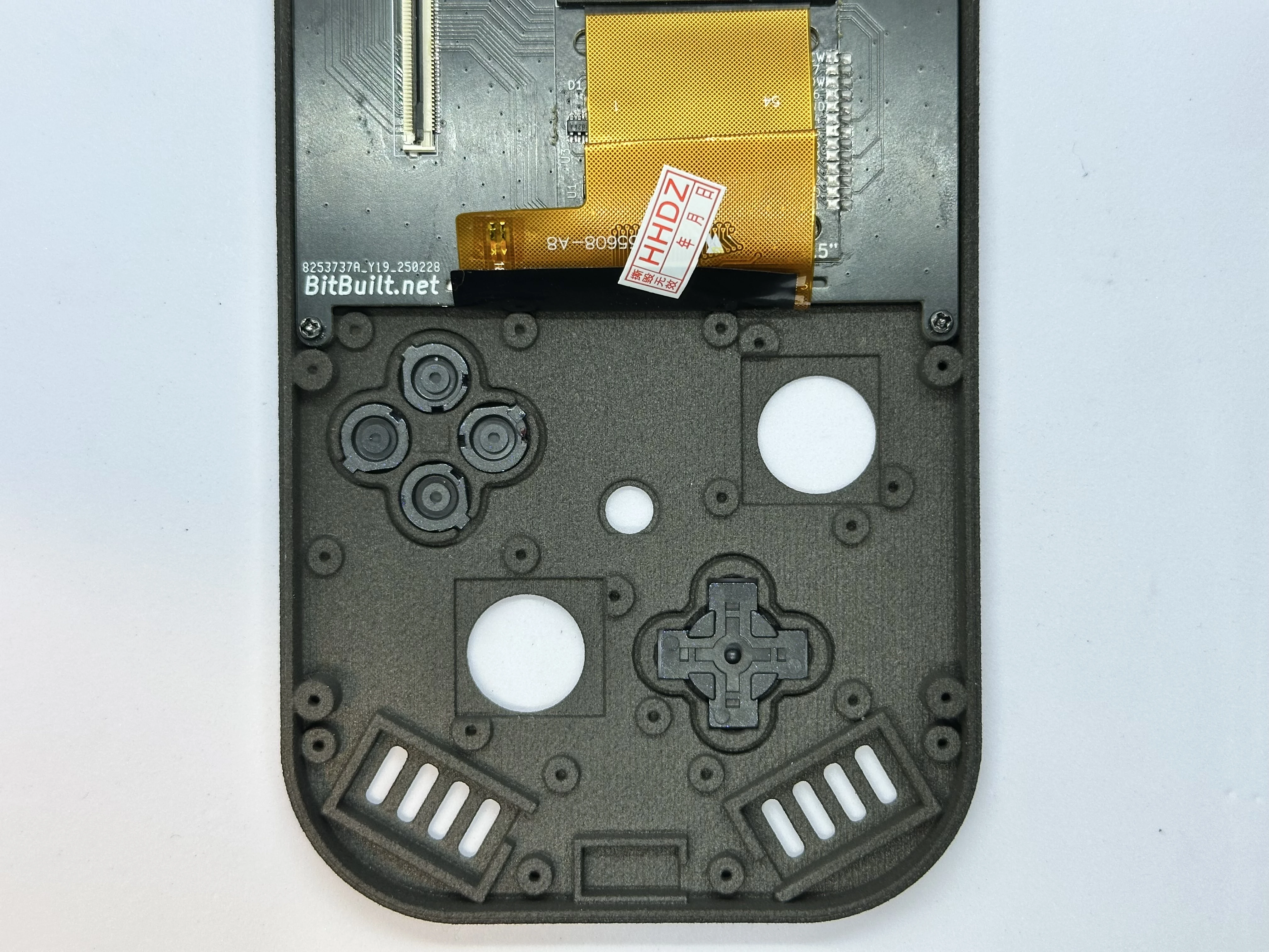
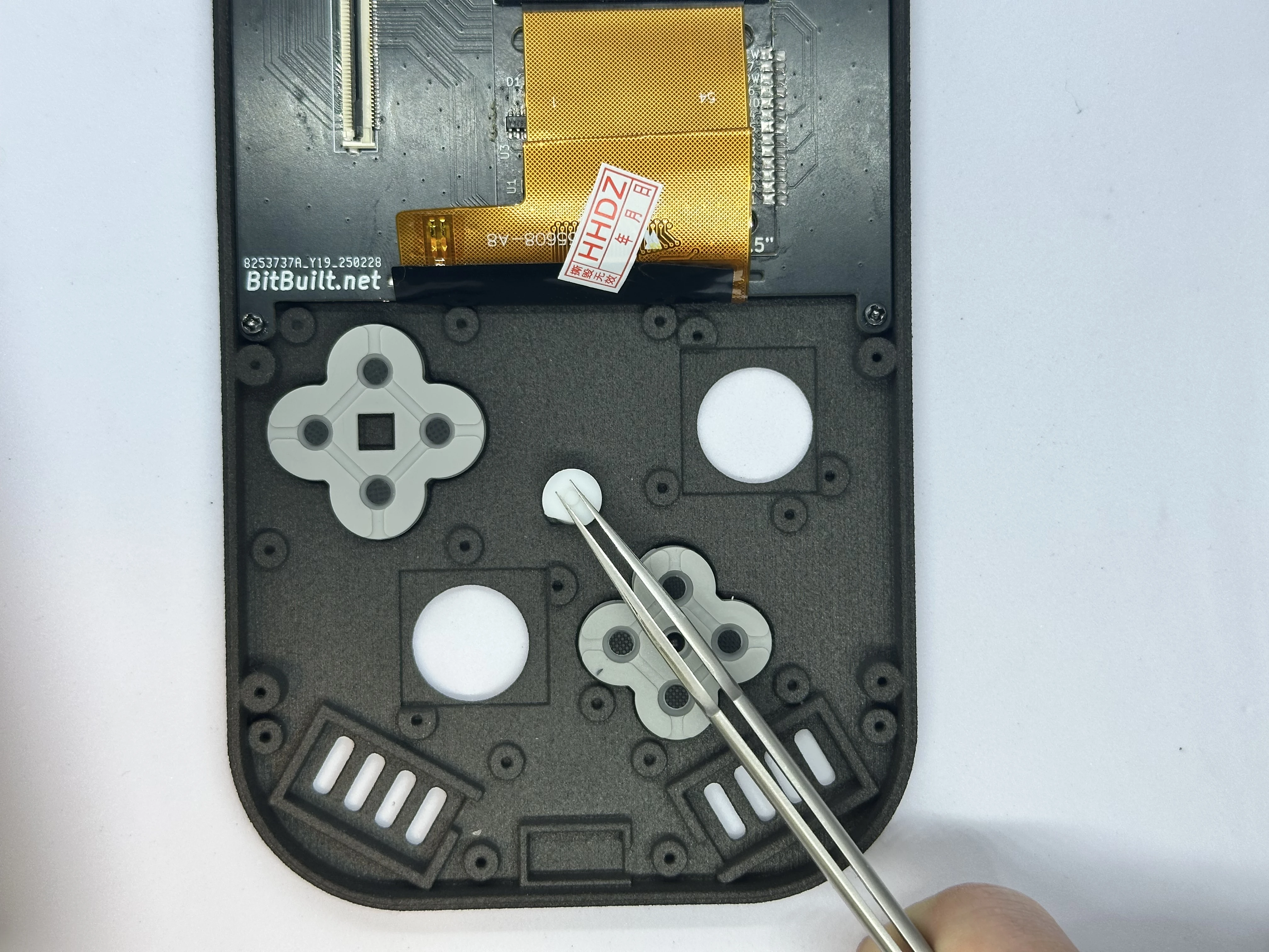
- Retrieve the DS lite buttons and D-pad from Bag T3. Place the DS lite buttons and D-pad in their respective slots. The buttons have notches to ensure correct orientation. The D-pad, however, can be installed in any orientation.
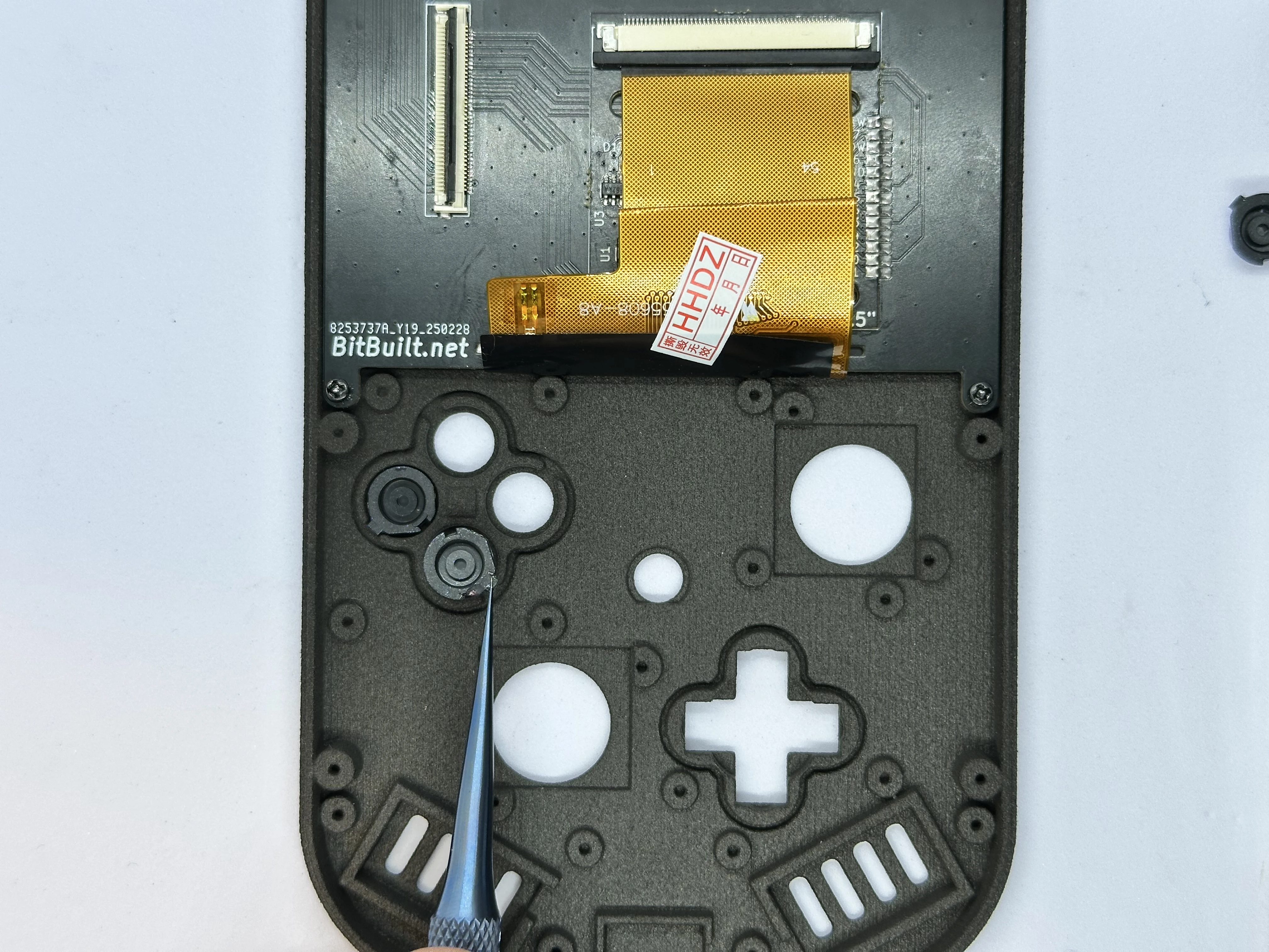
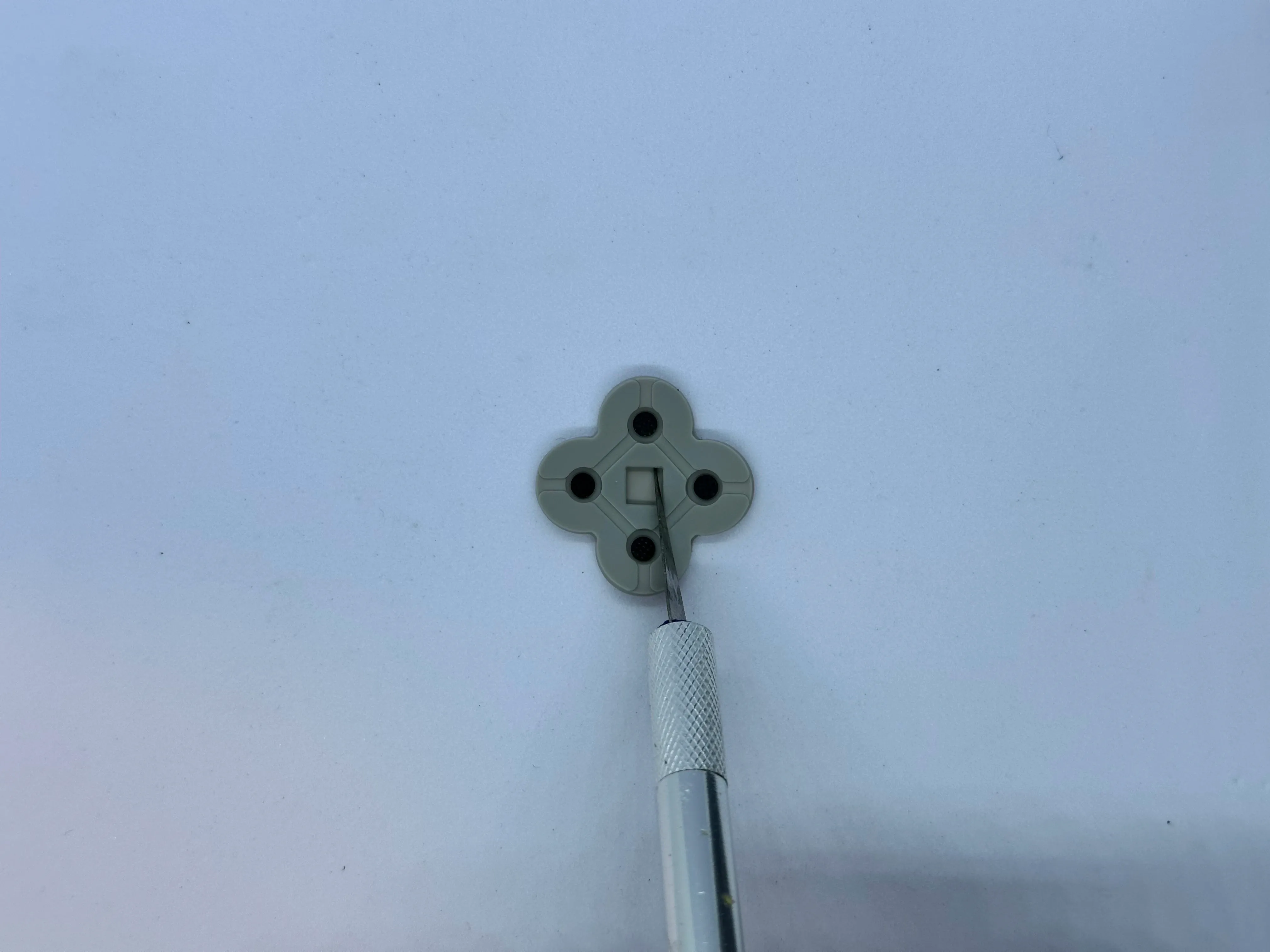
- Trim the membrane for the buttons. This is a required step - it is done to create a tighter fit with the shell. The square in the middle of the membrane can be completely cut out using an X-Acto knife with a
#2blade.
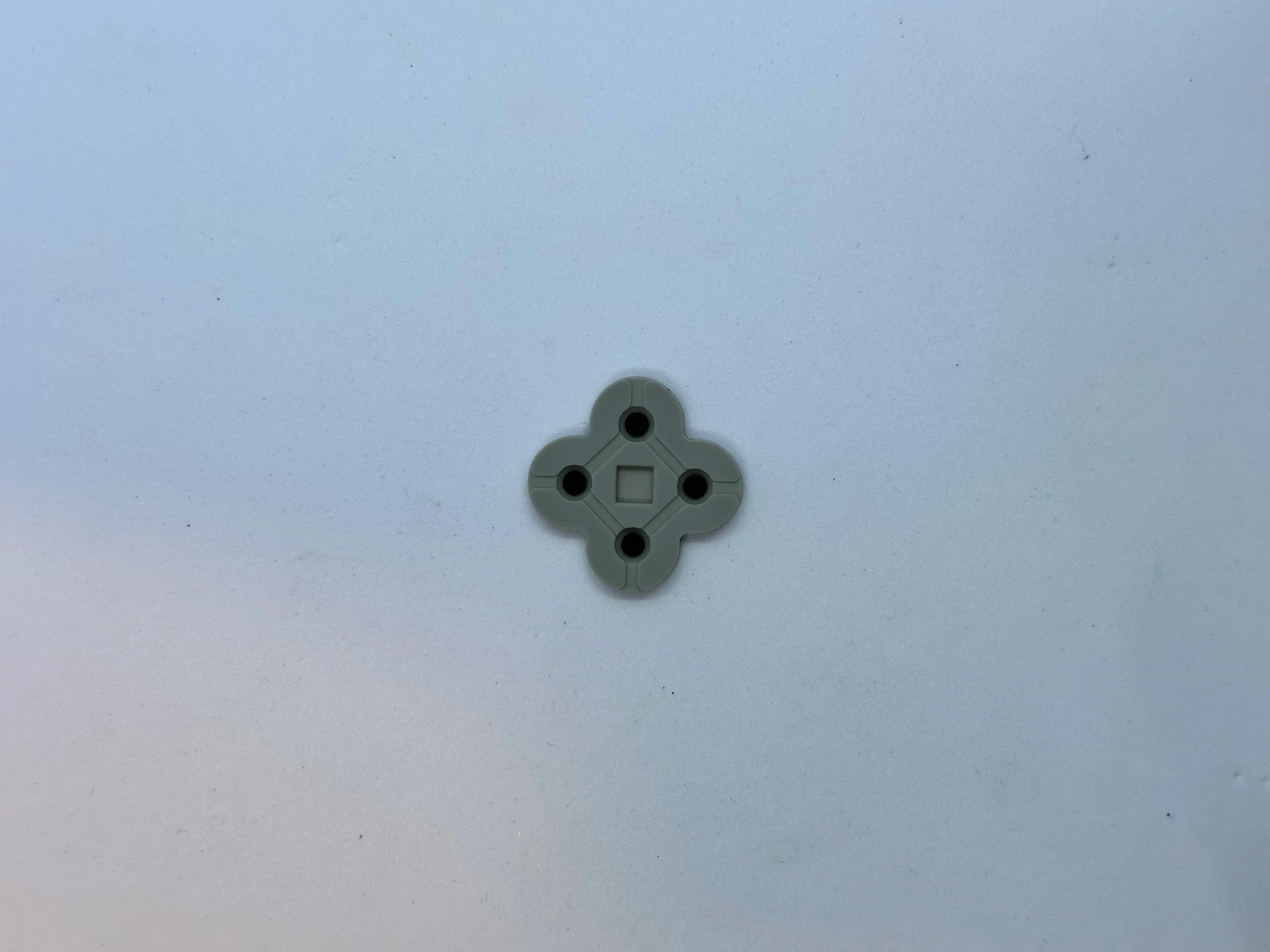
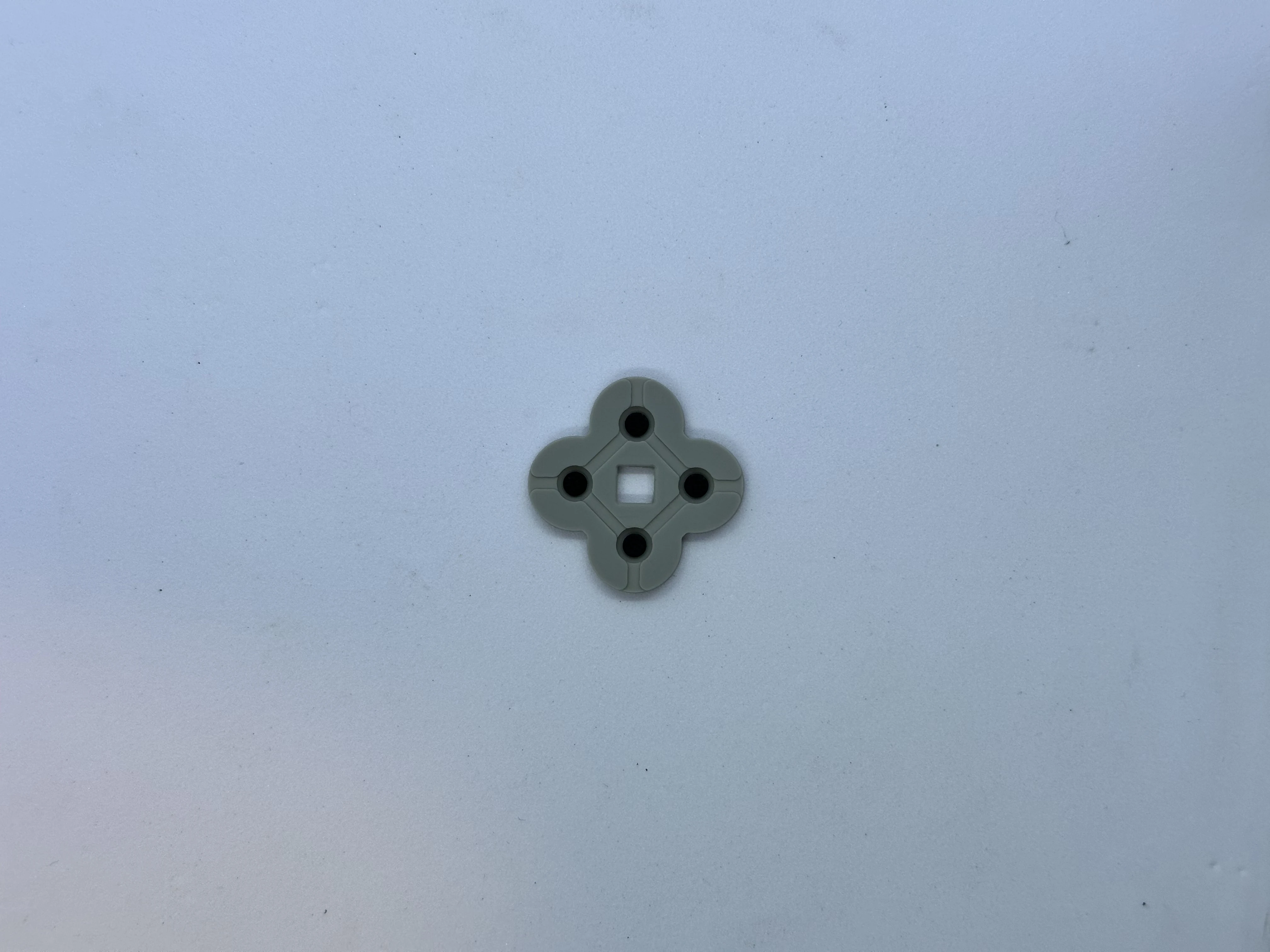
- Place the membranes for the buttons and D-pad. Then, place the center Start button. If the button's membrane does not sit flat, consider trimming the square a bit wider.
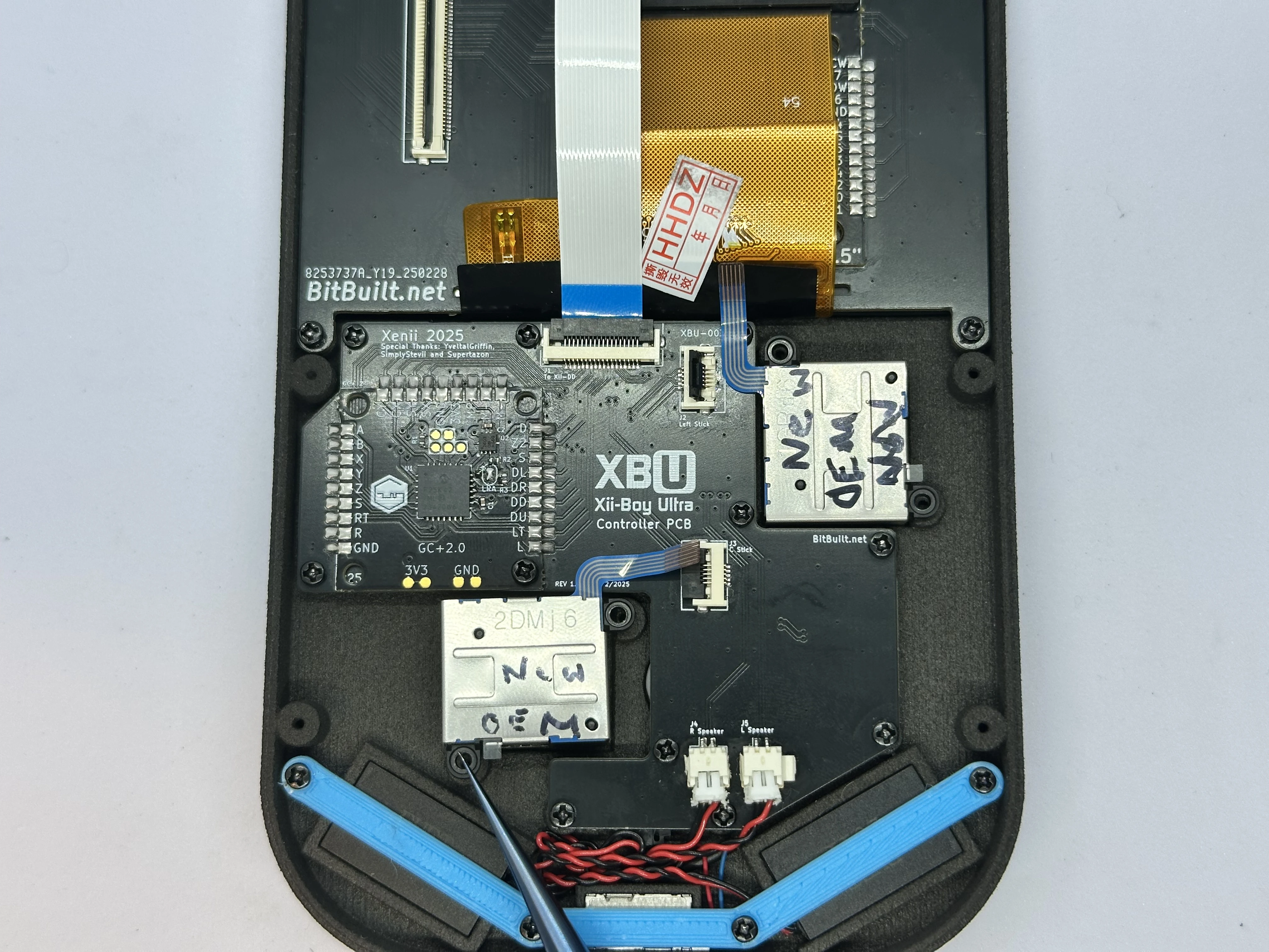
Controller PCB (XBU-003)
Note
The order of the following steps is not optimal and needs to be updated. Use as reference only.
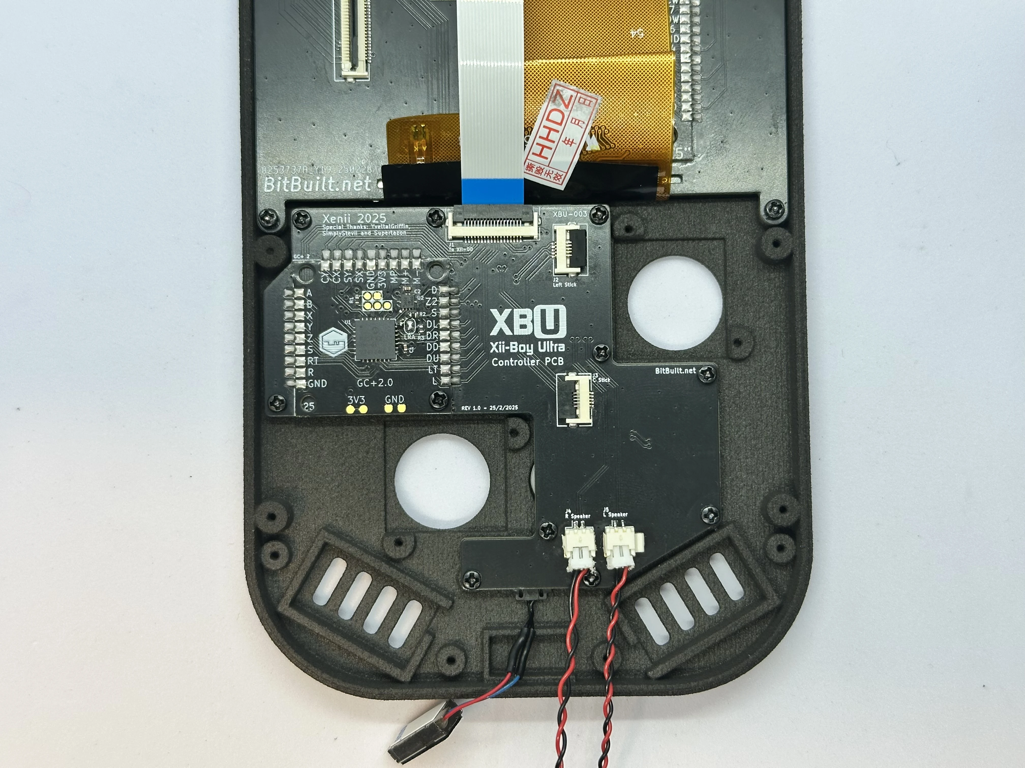
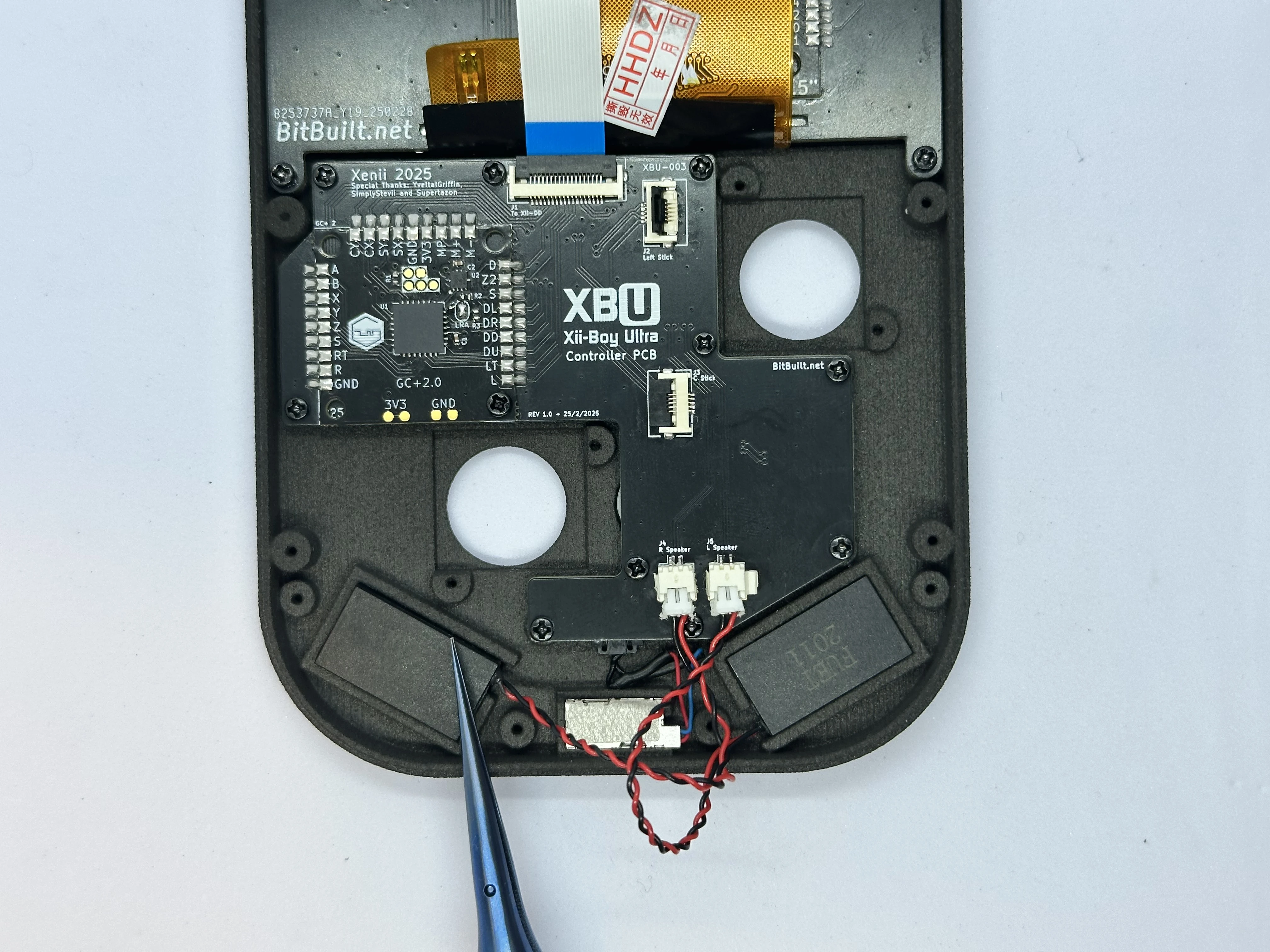
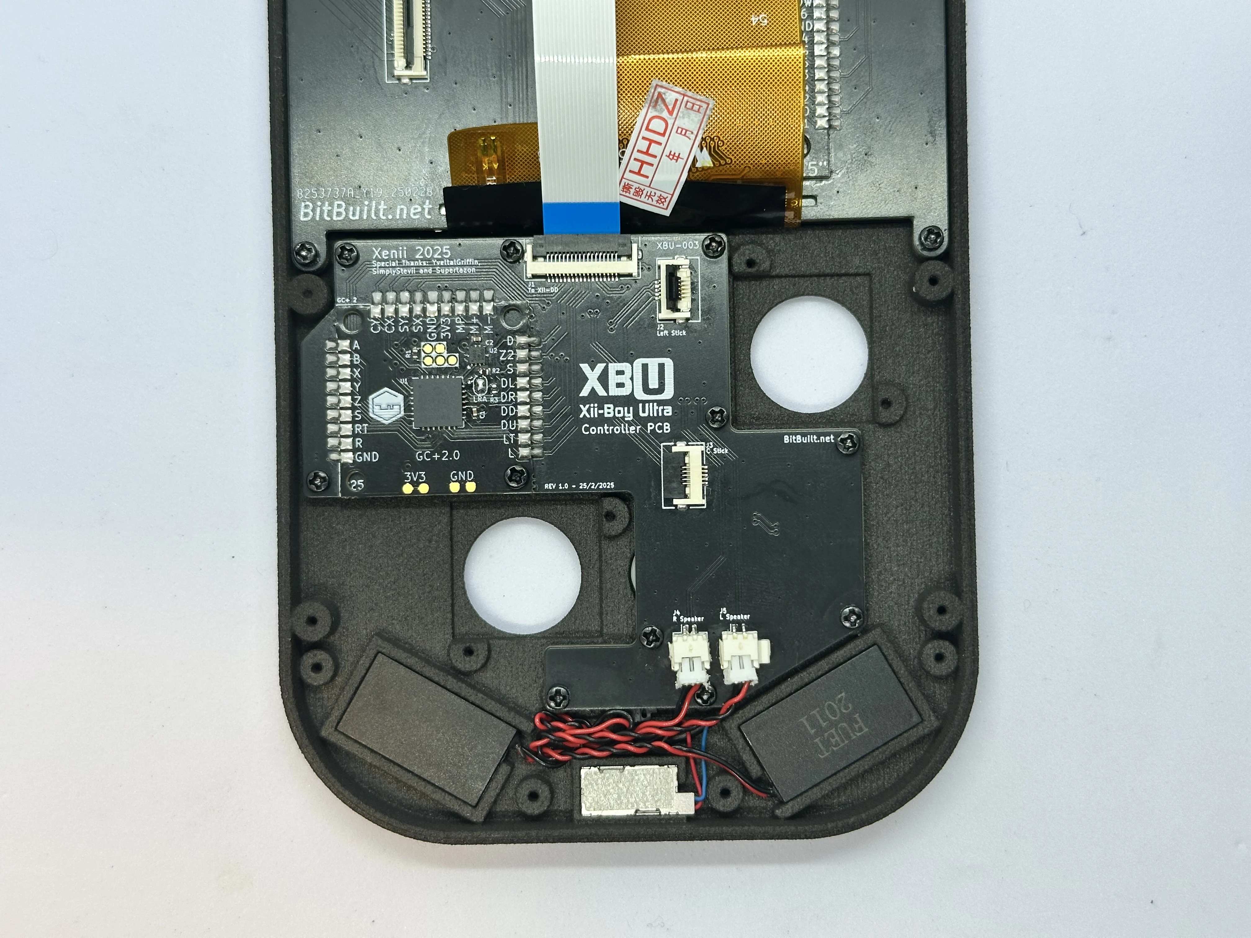
- Retrieve the left and right speakers from Bag T6 and connect them at the bottom of the PCB. They push directly in and will stay snug there.
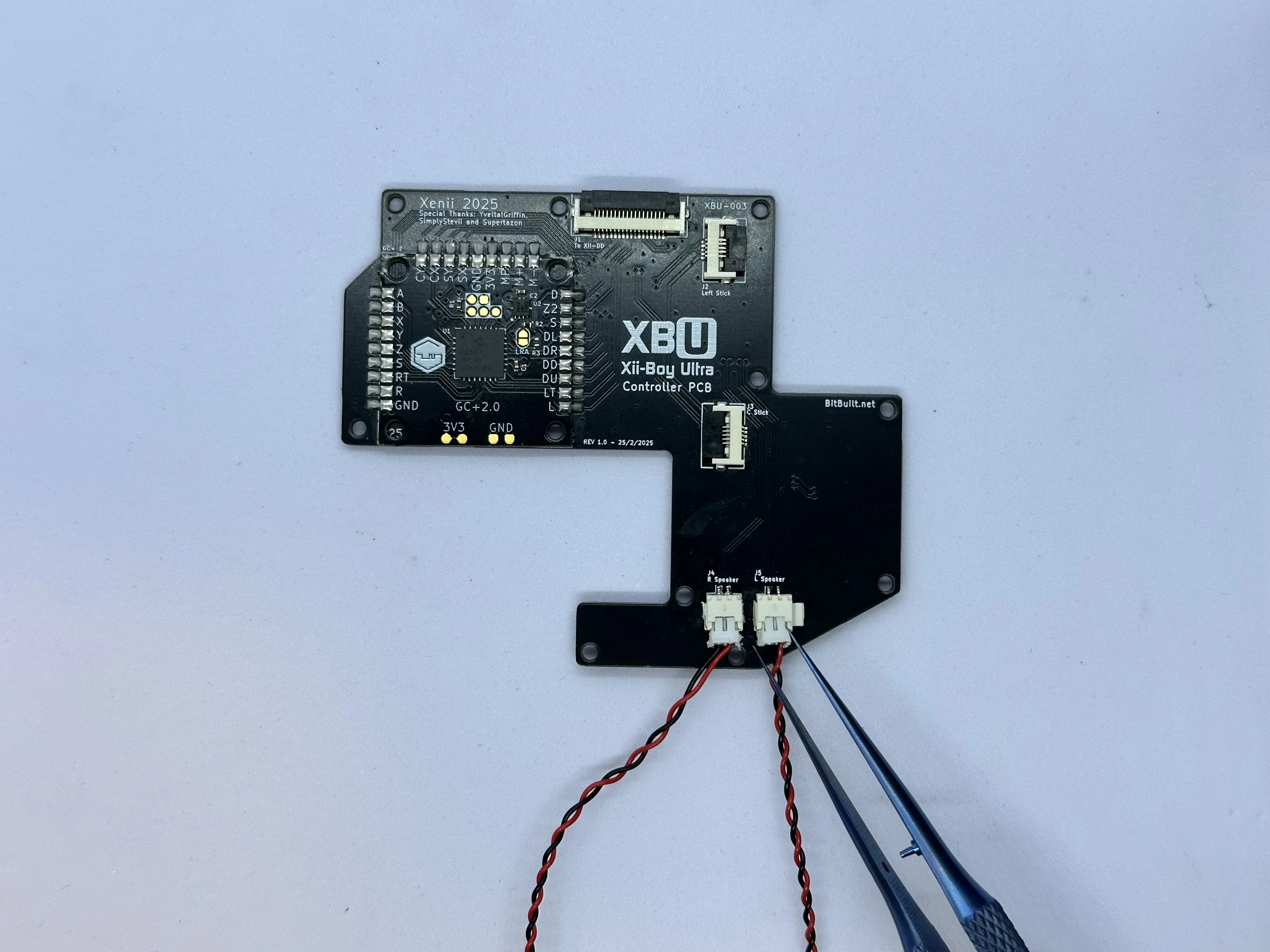
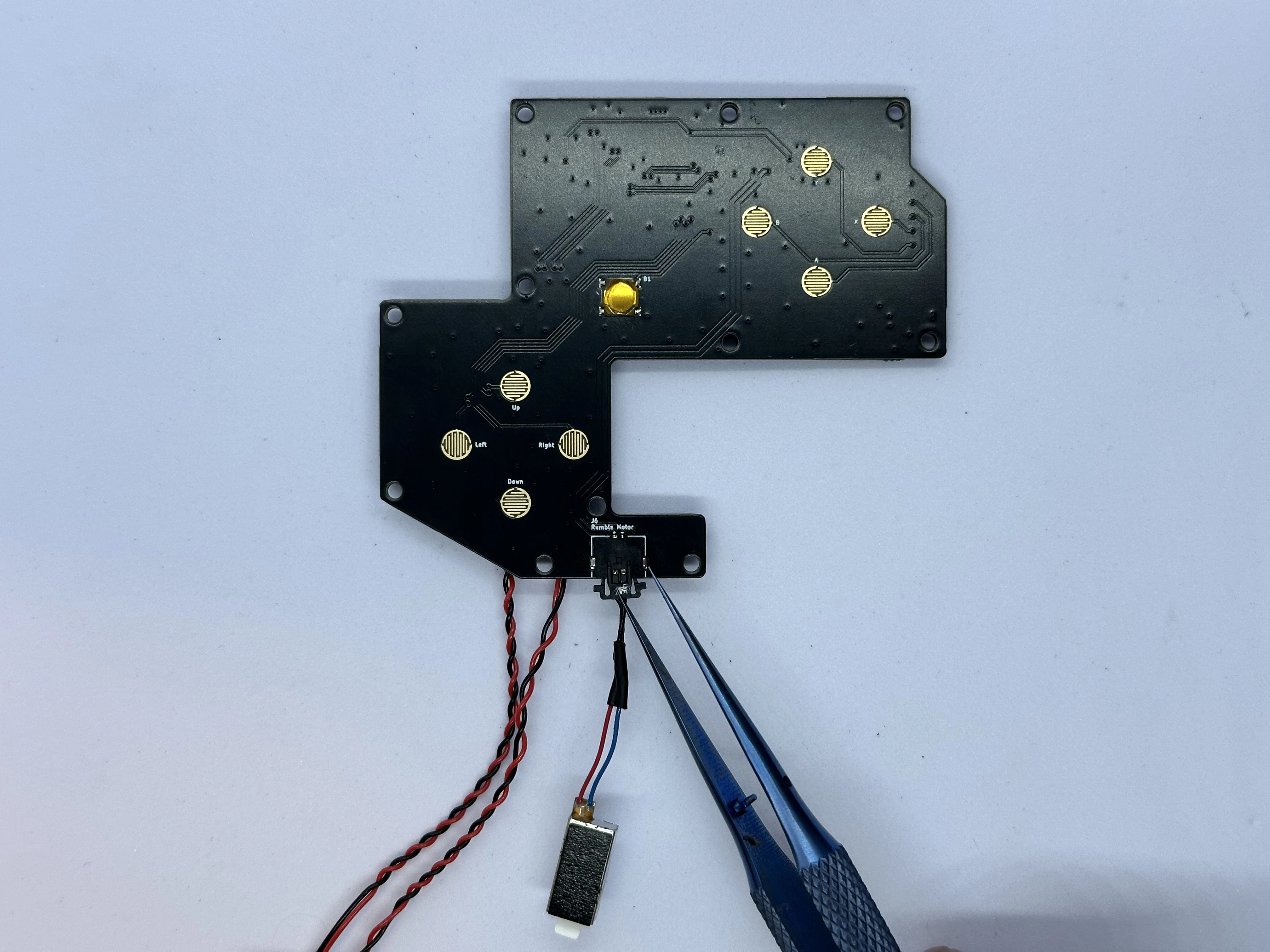
- Retrieve the rumble motor from Bag T5. Connect the rumble motor to the picolock connector at the bottom of the Controller PCB. The picolock connector is keyed and will only insert in one direction. Do not force it. Take note of the polarity: The red wire on the rumble motor connects to the
+pad, and the blue to the-pad.
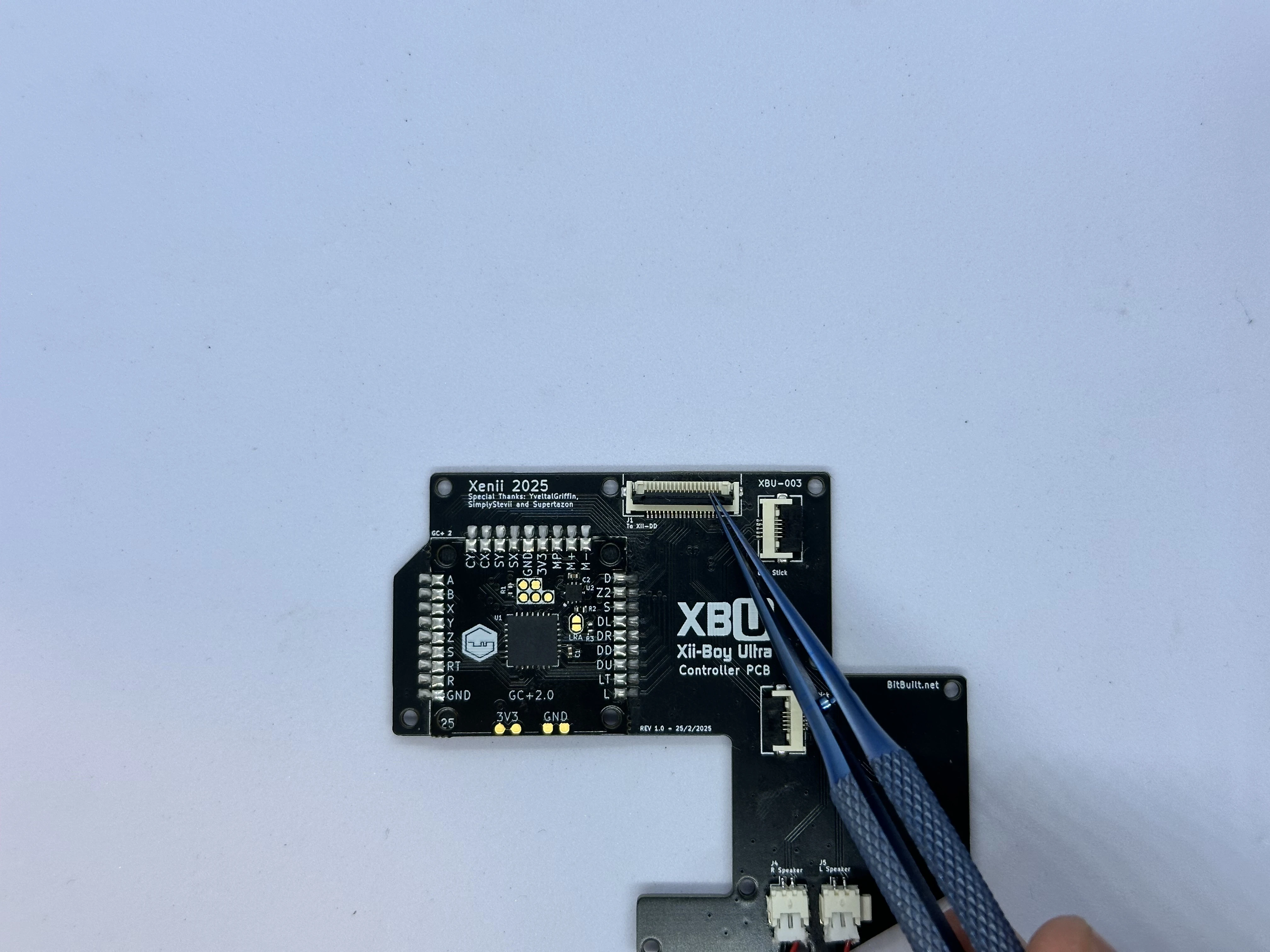
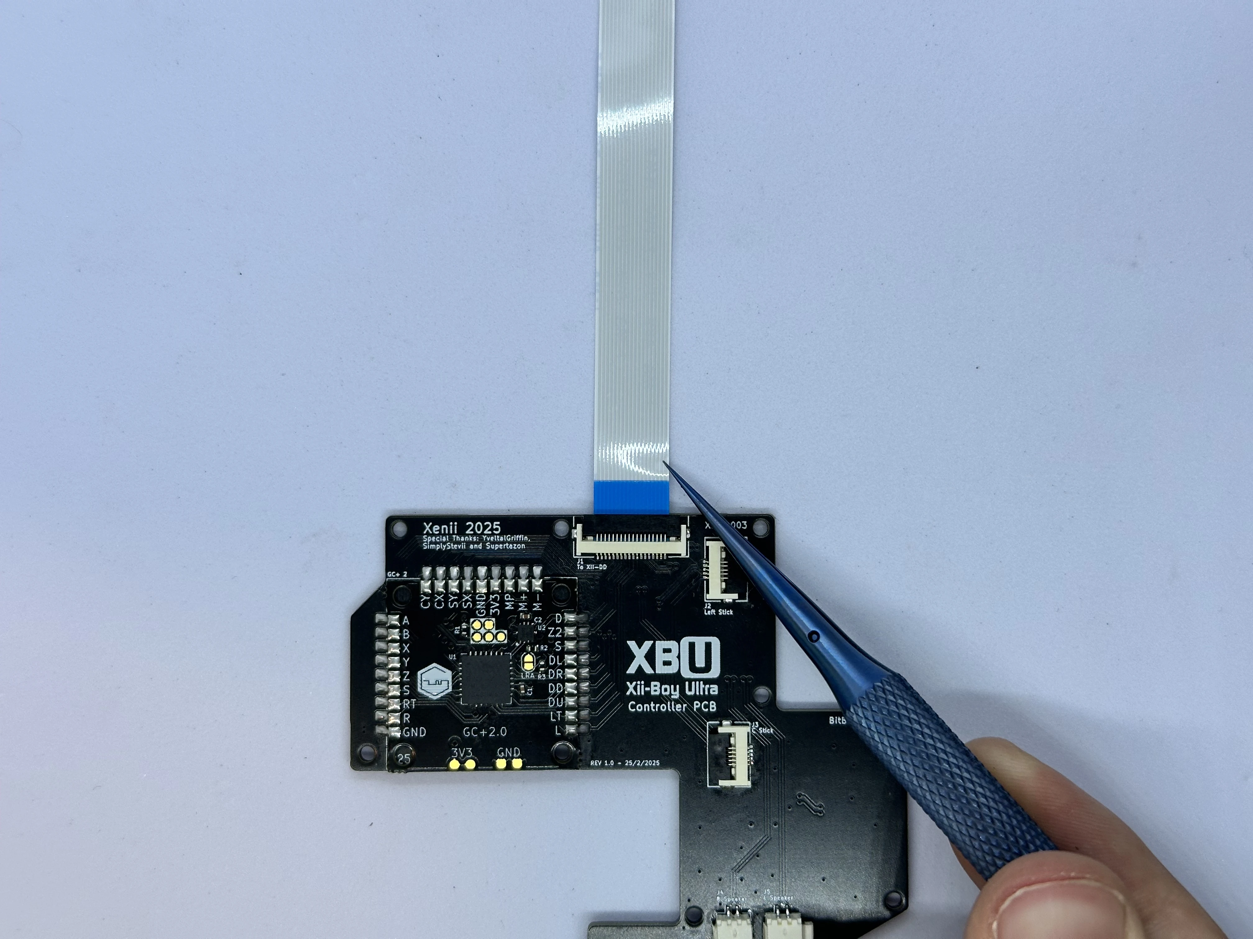
- Unlock the ZIF connector on the Controller PCB labeled
To Xii-DD. Retrieve an 18 pin FFC from Bag G5 and insert it with the blue stiffener facing up. Then, lock the connector.
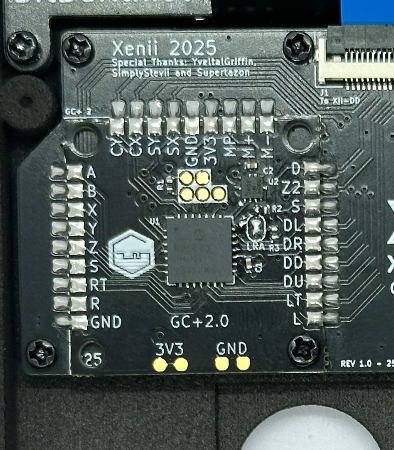
- Apply a small amount of flux to the
LRApads on the GC+2.0 PCB. Then, jump the two pads together by creating a solder bridge. Be careful not to damage any surrounding components.
Finishing Top Half
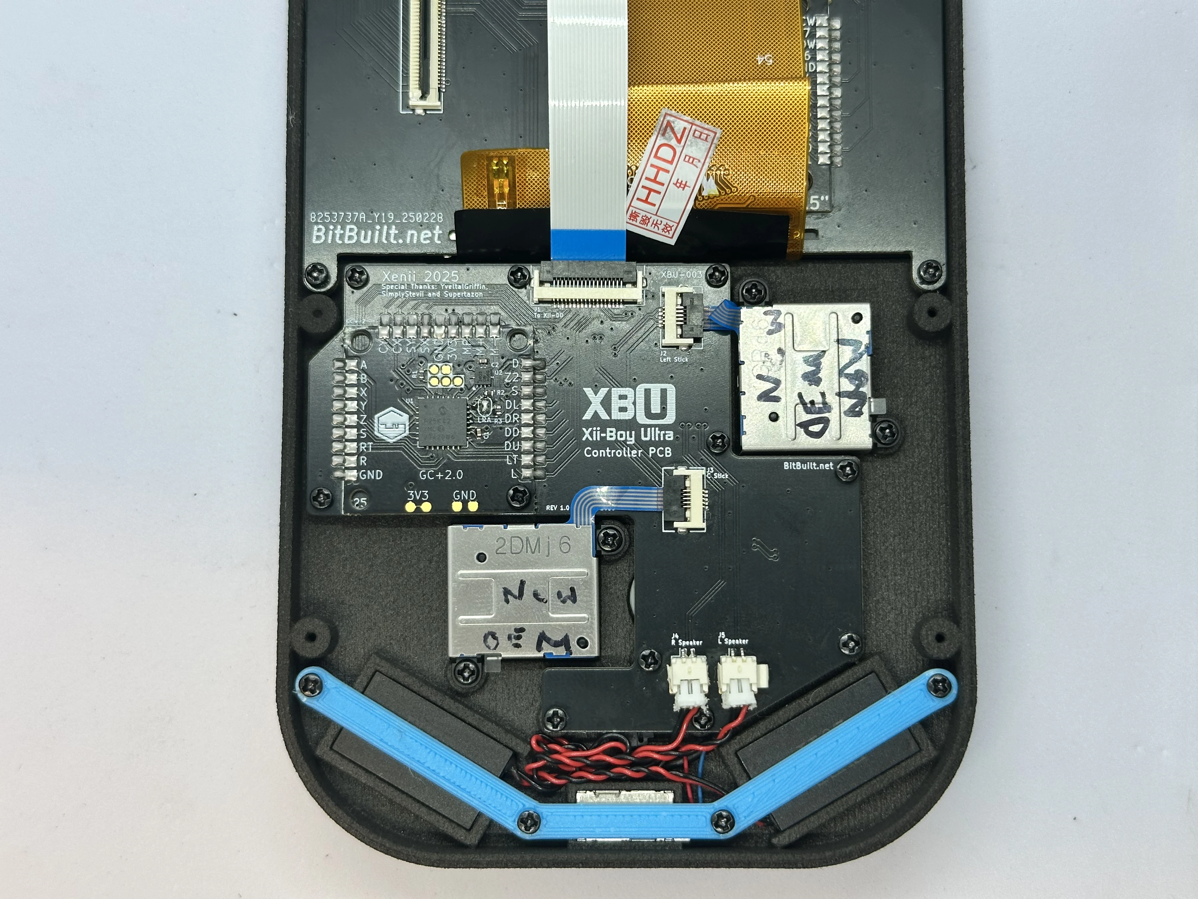
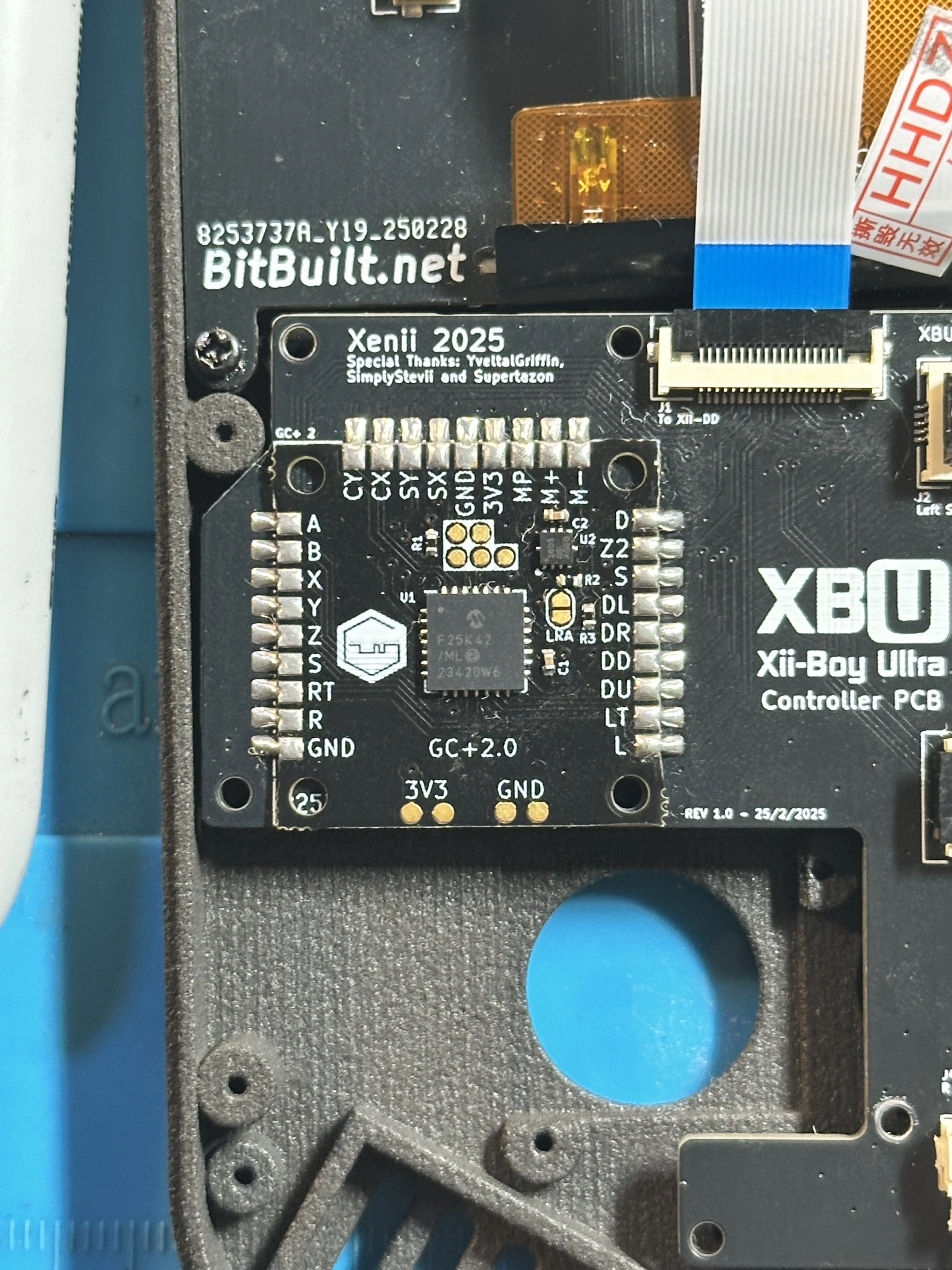
- Line up the completed Controller PCB with its screw posts. Ensure the cables for the rumble motor and speakers do not get caught underneath the PCB. Then, screw the board into place using eleven
4mmPhillips screws from Bag G3.
- On the Xii-DD PCB, unlock the 18 pin ZIF connector near the top and insert the FFC coming from the Controller PCB. Lock the ZIF connector when finished.
- Remove the sticker covering the adhesive backing on the rumble motor. Then, set the motor into its slot and tuck the wires under the PCB.
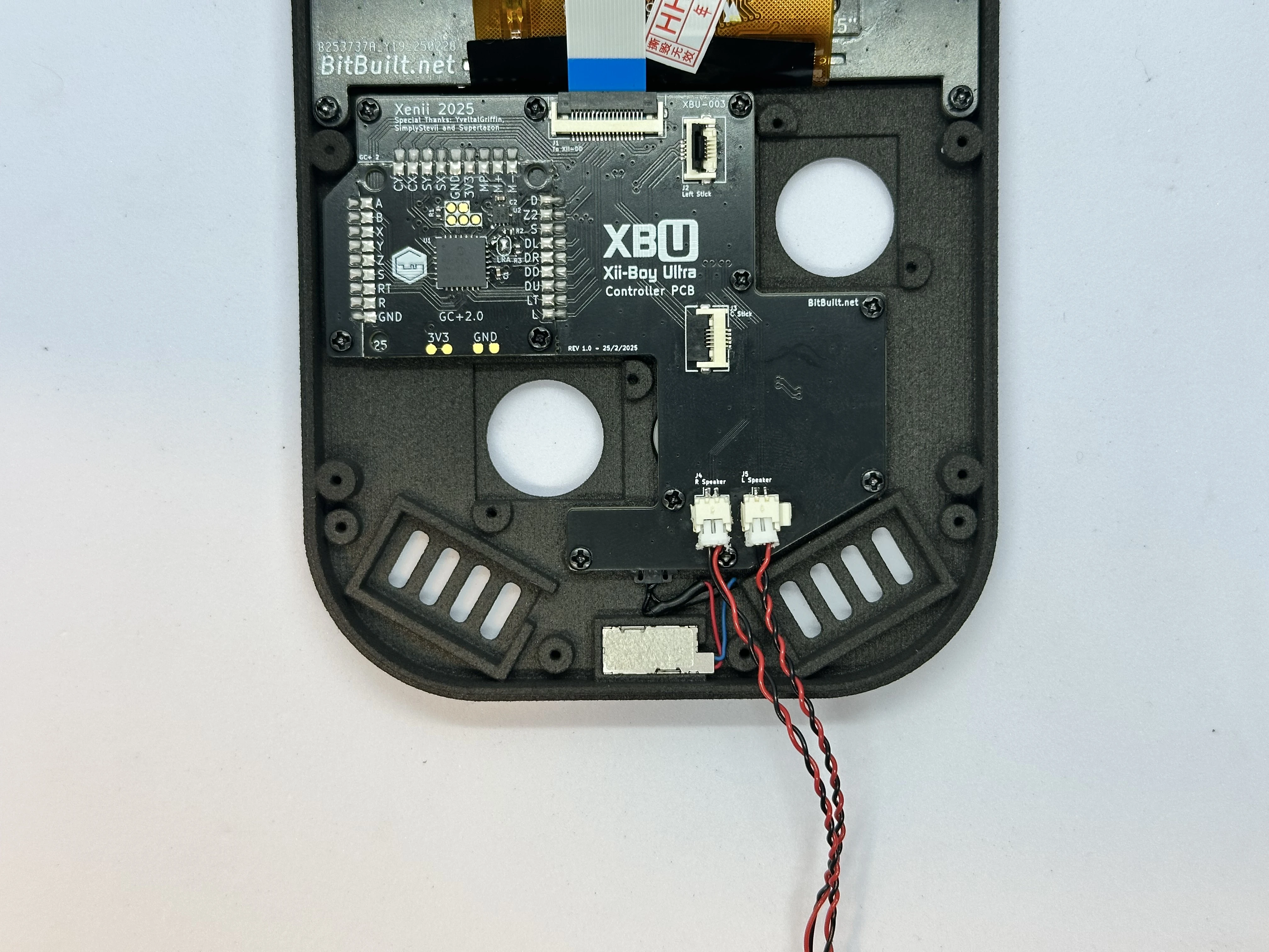
- Retrieve two speaker meshes from Bag T6. Place a
19mm x 9mmspeaker mesh into each speaker cutout. After that, place each speaker in its slot, and tuck the excess wire in between the rumble slot and the PCB.
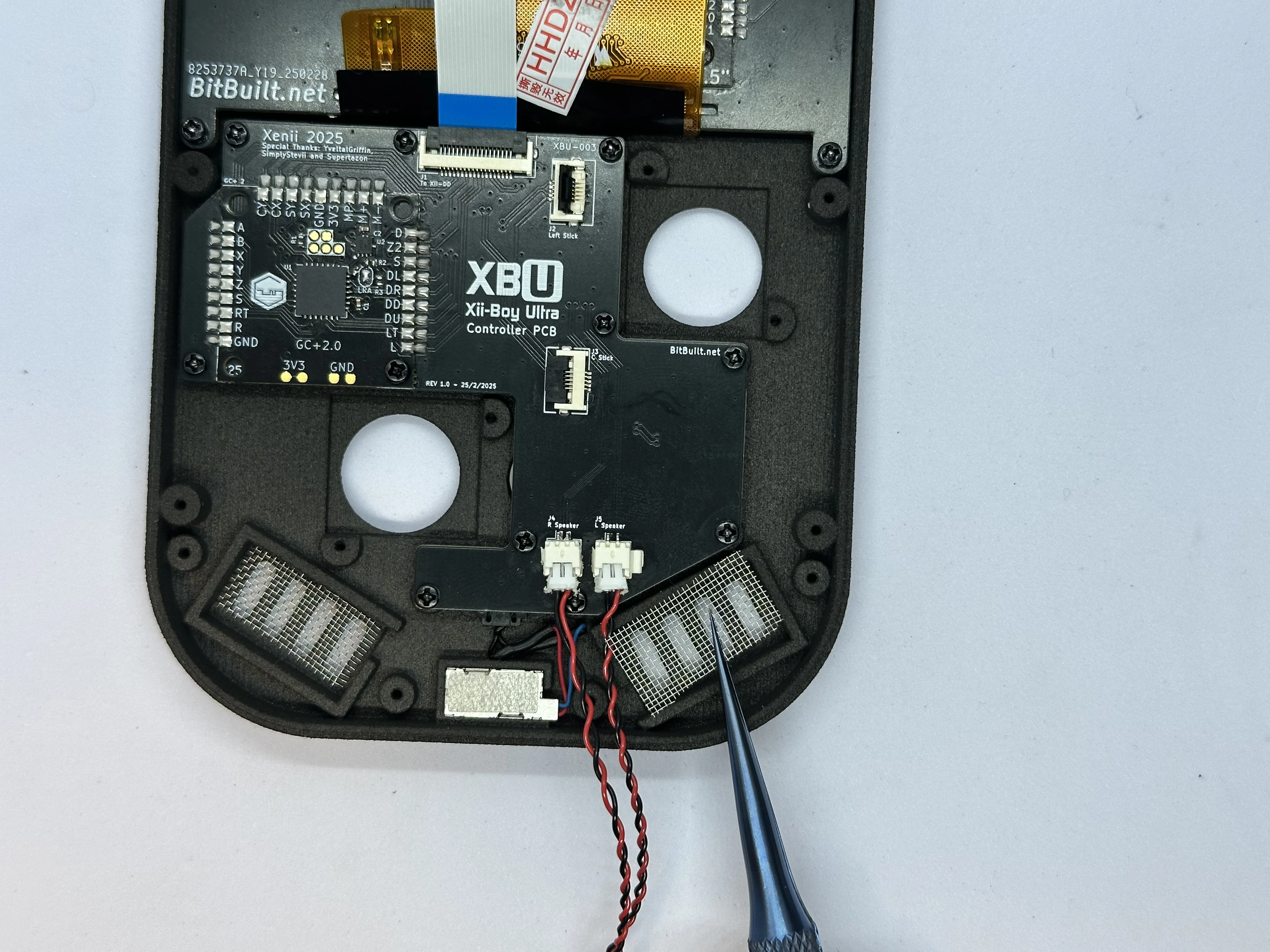
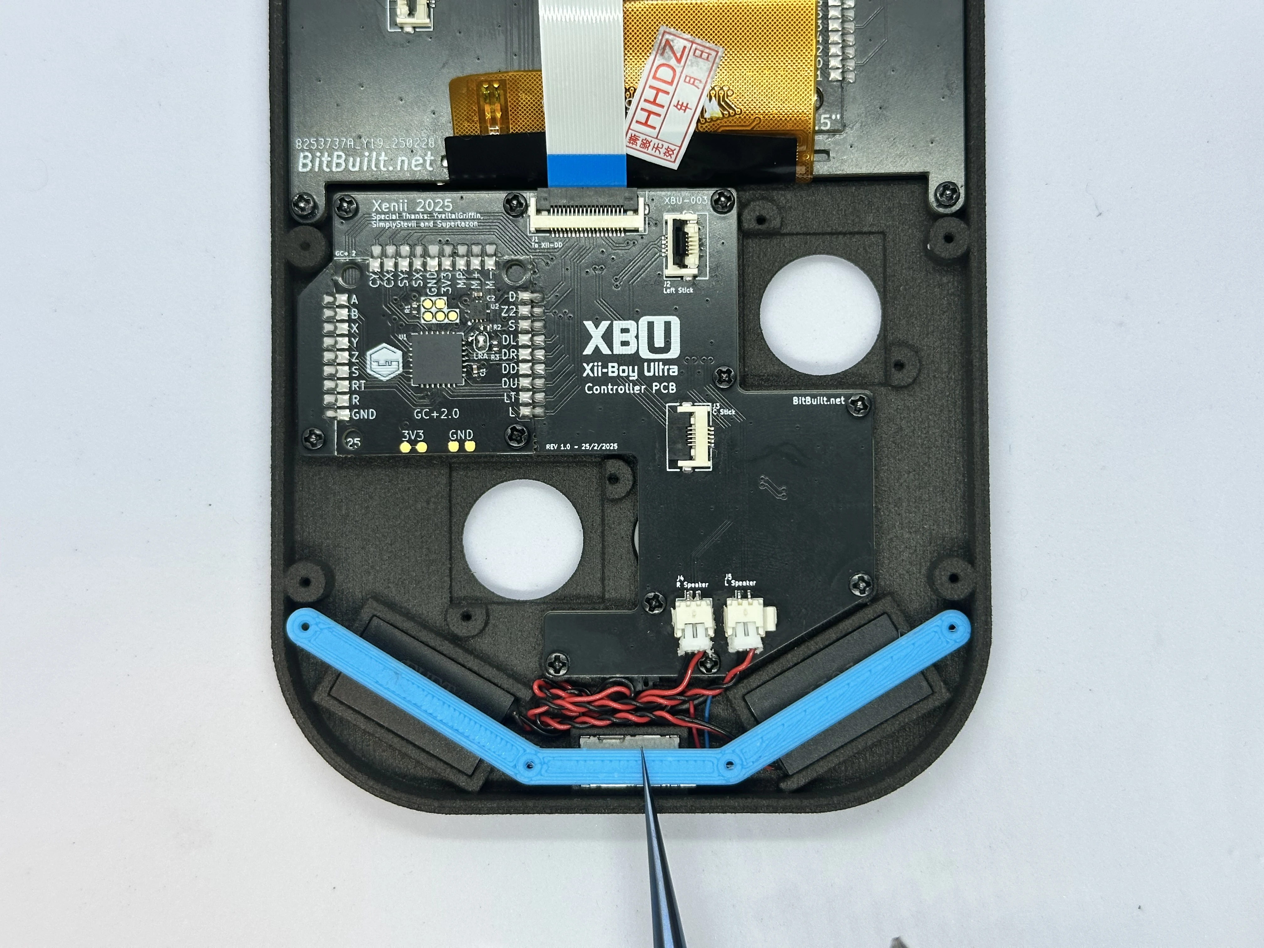
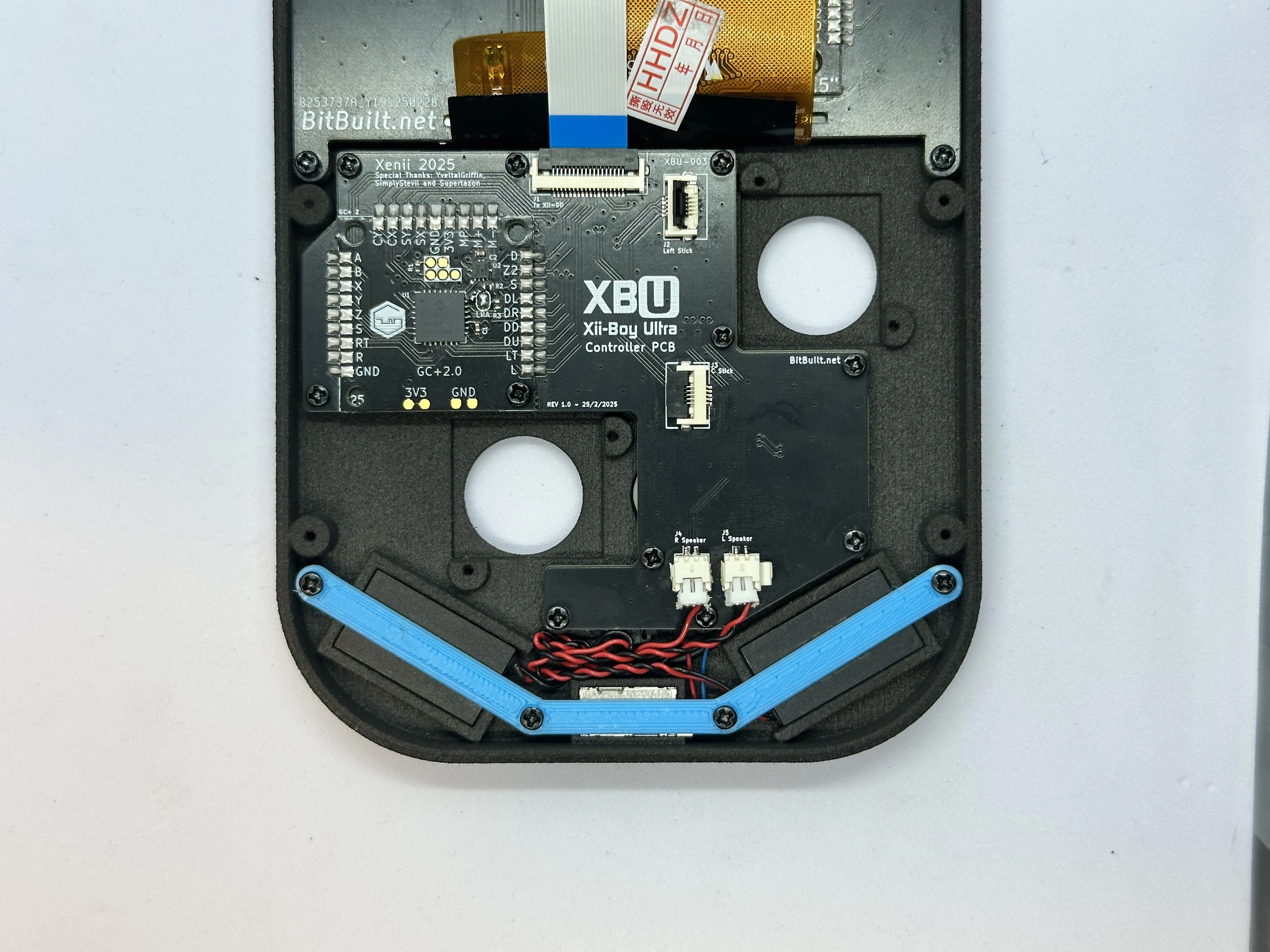
- Place the retention bracket over the speakers, rumble motor, and screw posts. Secure the bracket with four
4mmPhillips screws from Bag G3.
- Retrieve two Joy-Con Joysticks from Bag G2. Connect the joysticks to their ZIF connectors. Then, place the joysticks over the screw posts and secure them with two
4mmPhillips screws each from Bag G3. The left joystick (closest to the RVL-DD) will need to have its cable folded in order to fit.