
Xii-Strip & Xii-Flex Install
Both Xii-Strip and Xii-Flex Ultra are crucial to the trimmed Wii's functionality. While Xii-Strip supplies power to the voltage rails on the trimmed Wii, Xii-Flex Ultra breaks out all the neccesary connections from the vias on the Wii to a 50 pin connector on the Main PCB. Because of how many connections are broken out, it can be easy to bridge connections, so follow each step exactly and check for bridges before continuing. Be prepared to reflow as necessary.
Installing Xii-Strip
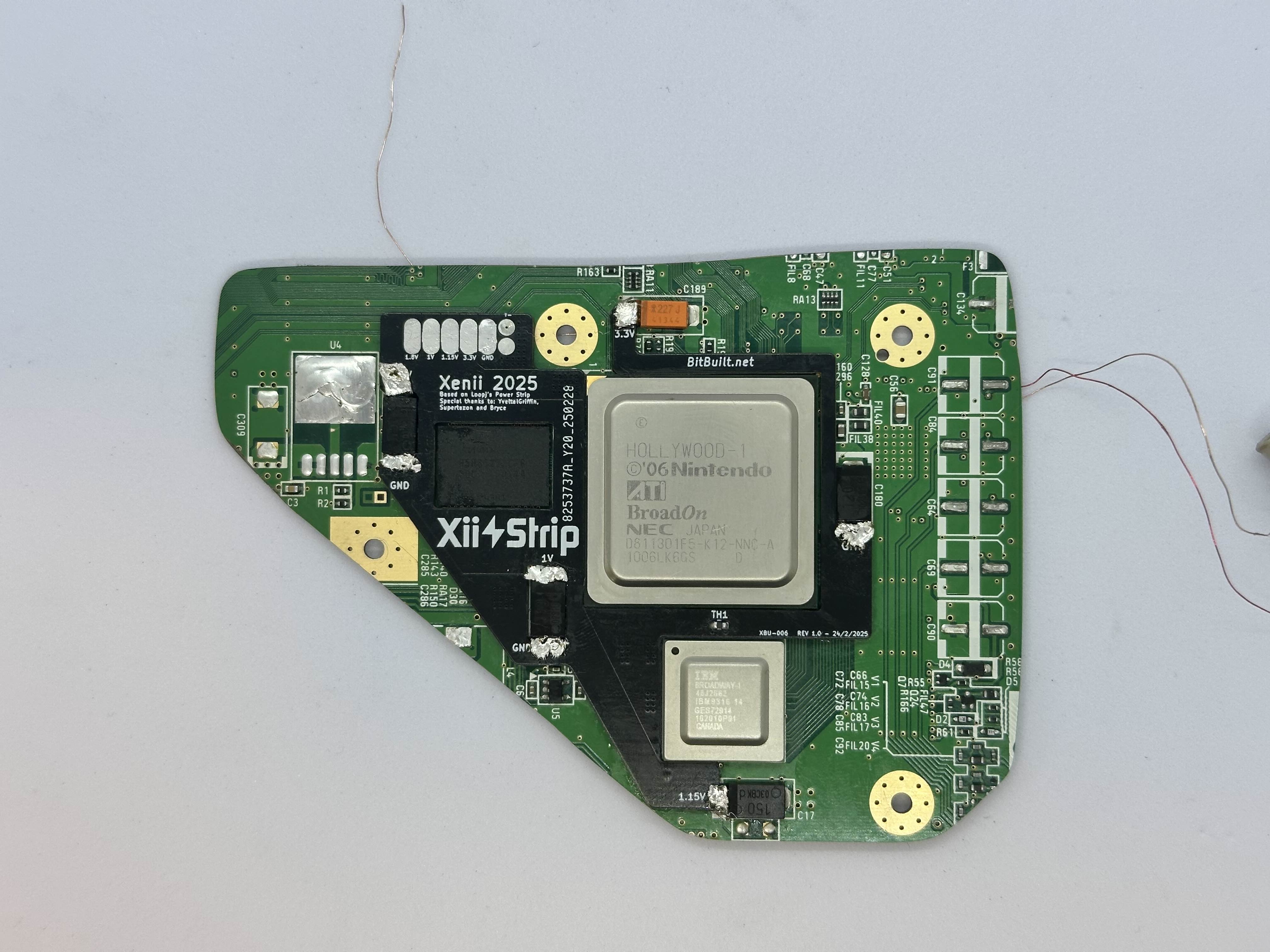
Retrieve Xii-Strip FPC from Bag B7. Align it on top of the trimmed Wii so that it lays directly against the PCB.
Refer to General Soldering for a more extensive guide on the process of soldering joints.
Heat the 1.8v pad on the Wii until the solder melts, then adjust the soldering iron so that it heats both the pad on the Wii, and the pad on Xii-Strip. Add solder to the joint between the iron tip and both pads, allowing it to melt briefly before removing the solder roll.
Repeat the process for the other highlighted pads, ensuring that Xii-Strip remains flush with the trimmed Wii before continuing with each pad. If Xii-Strip flexes at any point, reflow each pad while putting pressure on the board so that it is completely flat against the trimmed Wii.
Installing Xii-Flex Ultra
Flip the trimmed Wii so that the bottom side is facing up. Refer to Scraping Vias and scrape each of the highlighted vias to expose the copper beneath the soldermask.
Refer to Flex Soldering for the following steps.
Apply solder and distribute it so each via is fully tinned. Ensure there is no bridging between adjacent vias.
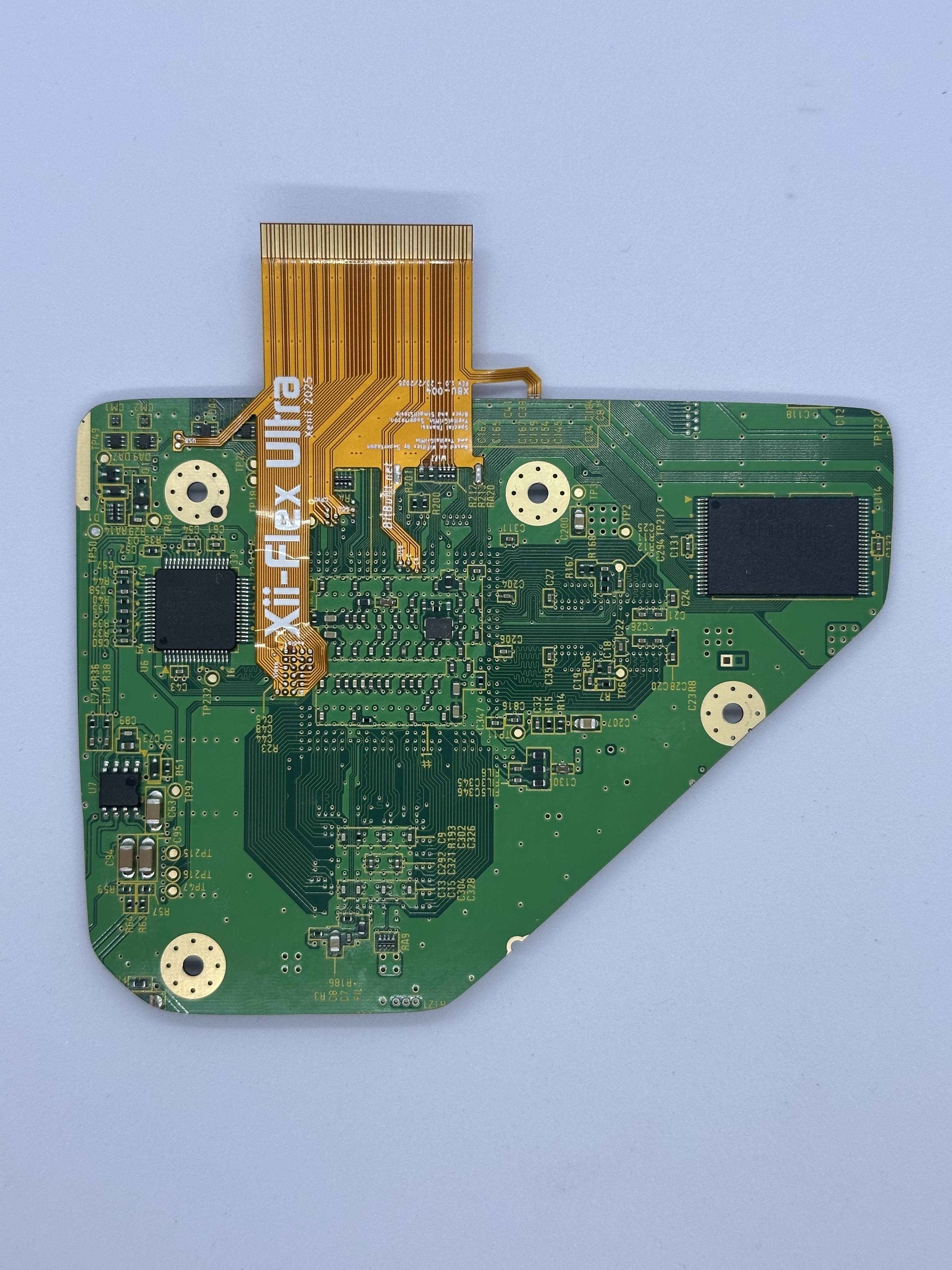
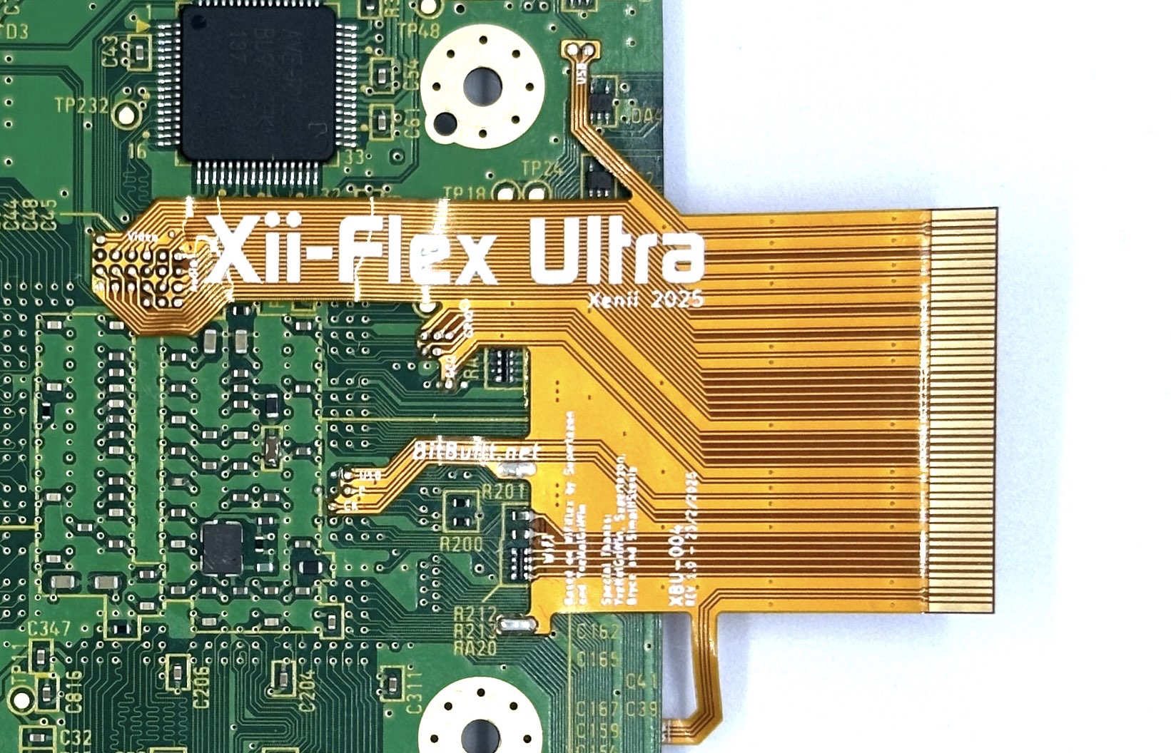
Retrieve Xii-Flex Ultra from Bag B6. Align it according to the diagram below, and hold it in place using tape. The Bluetooth connections bend around to the top side of the Wii. Ensure that resistors RA20, R213 and R212 are aligned with the castellated edges on Xii-Flex Ultra before continuing.
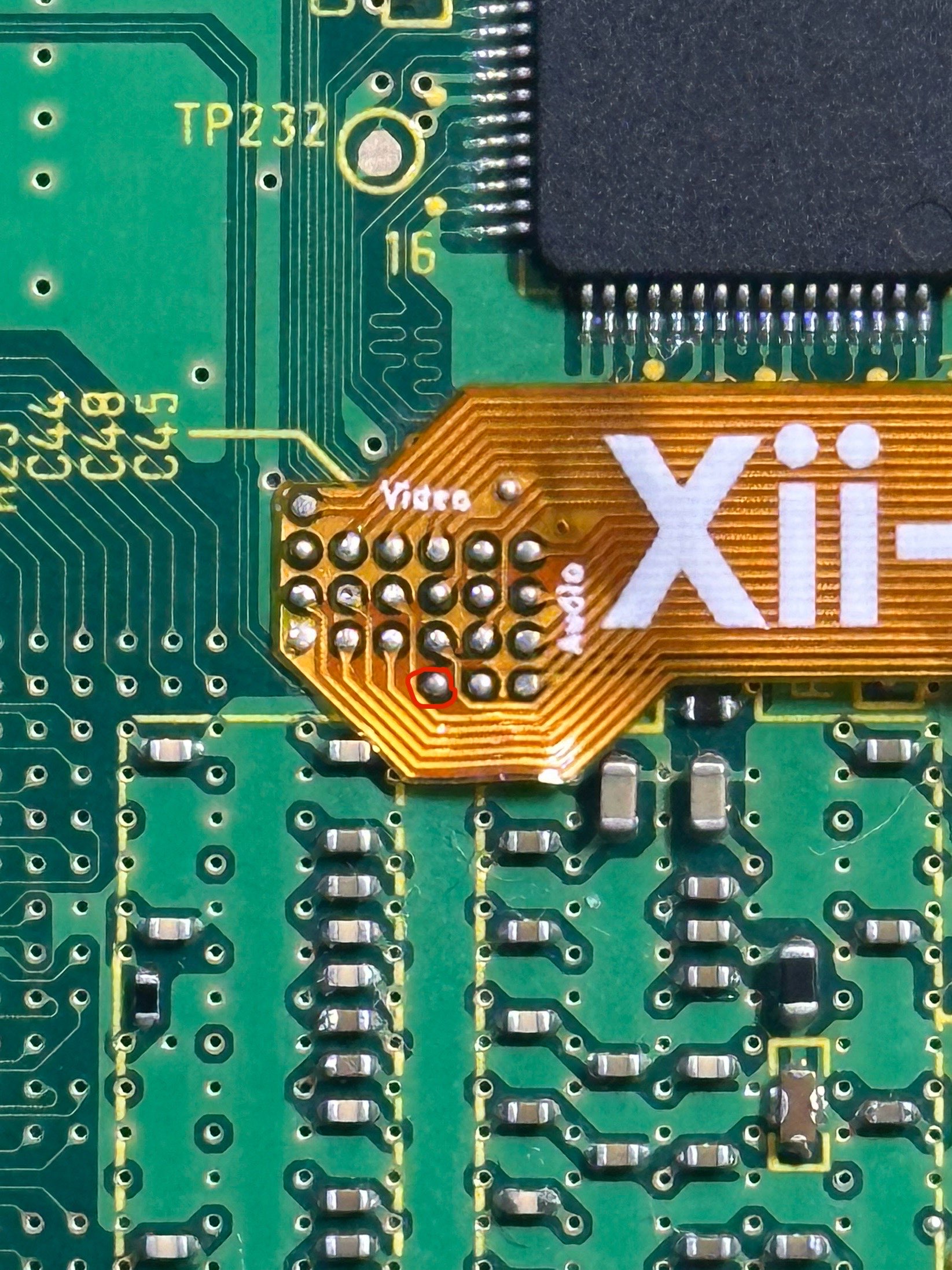
- Solder the GPU vias. Don't use an excessive amount of solder, as that increases the chance of hidden bridges beneath the flex.
Repeat this process for the rest of the tinned vias on the bottom, starting with USB. Once each tinned via is soldered to Xii-Flex Ultra, solder to resistors RA20, R213 and R212.
Solder the
3.3VandGNDpads on Xii-Flex Ultra to the Wii. Ensure these pads are fully soldered, as it may take longer for the Wii to heat up.
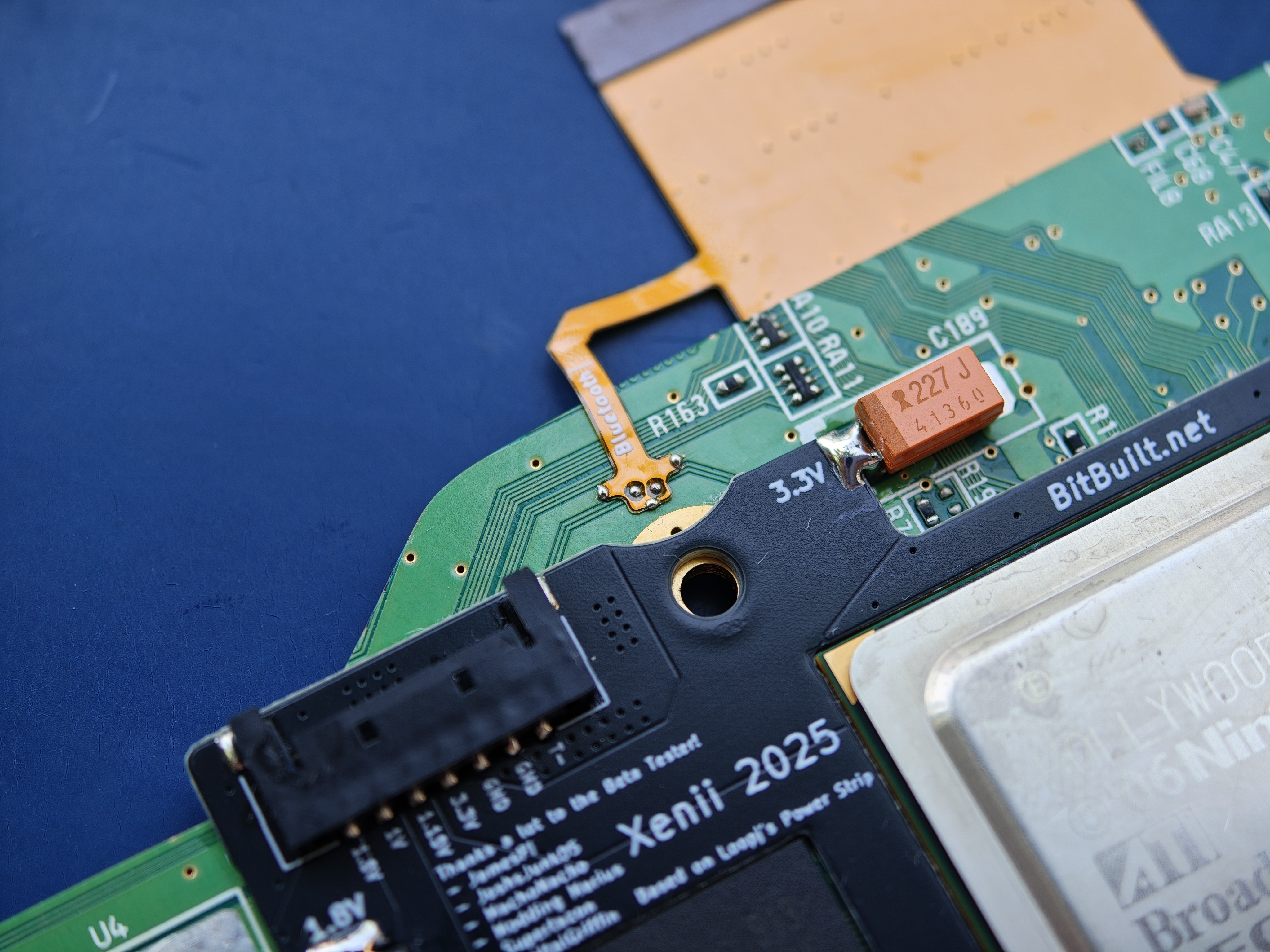
Flip the trimmed Wii so that the top side is facing up. Align the Bluetooth leg of Xii-Flex Ultra on the top side of the Wii to see where the vias on the flex are positioned.
Move the Bluetooth leg out of the way, then scrape the Bluetooth traces in a staggered manner, in order to minimize the chances of connections bridging. Temporarily align the flex to view where each castellated edge is. Scrape the board in those locations.
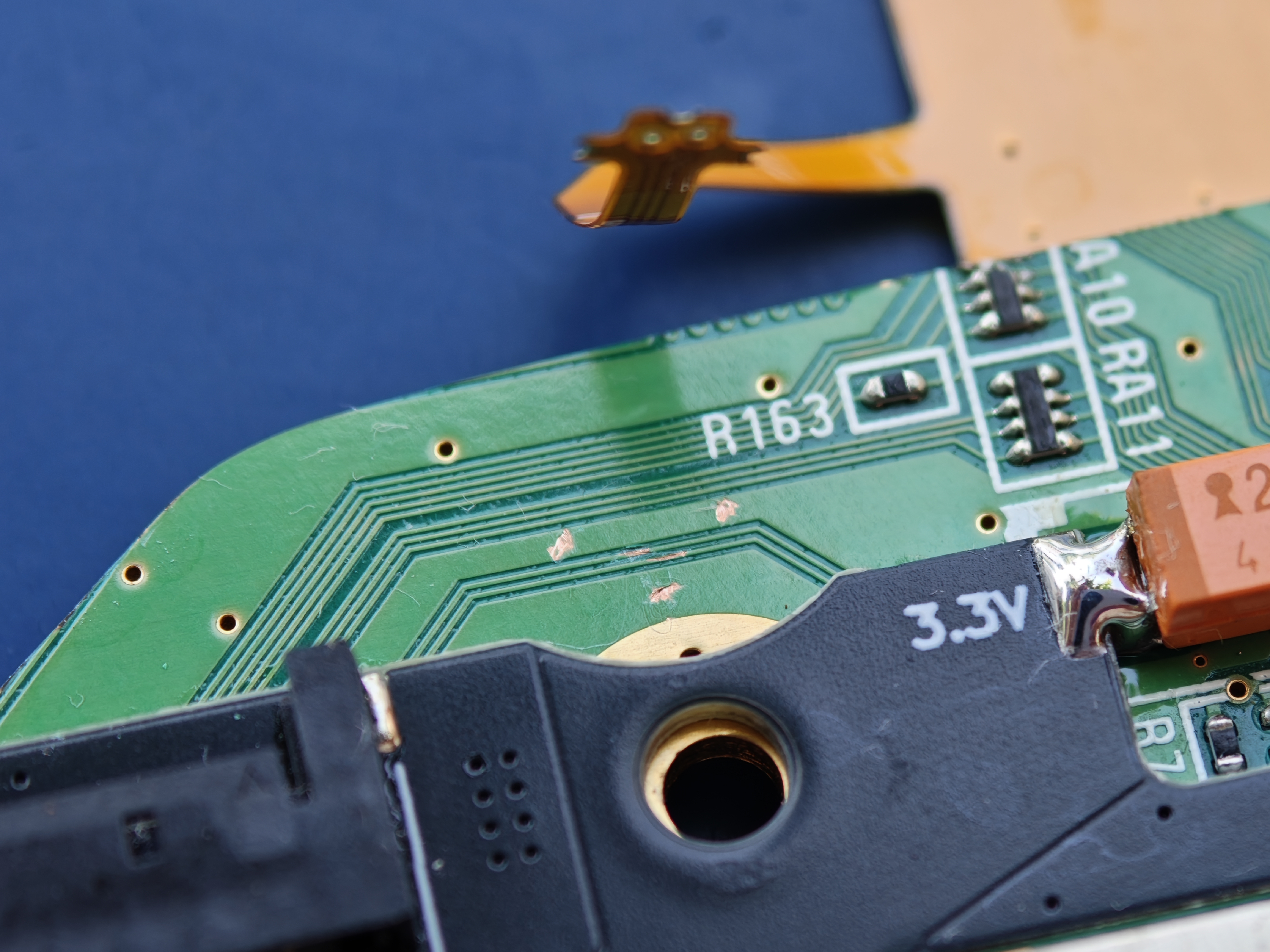
- Realign the Bluetooth leg, hold it down with tape, then solder both Bluetooth traces. Check for continuity and if they are bridging before continuing to solder the three
GNDpoints.